


8
SECTION III – INSTALLATION INSTRUCTIONS
equipment in space. Duct cross-sectional area
shall be same as opening free area.
3. Horizontal ducts. Minimum free area of 1
squareinchper2,000Btuperhourinputofall
equipment in space. Duct cross-sectional area
shall be same as opening free area.
Alternate method for boiler located within
conned space. Use indoor air if two permanent
openings communicate directly with additional
space(s)ofsufcientvolumesuchthatcombined
volumeofallspacesmeetcriteriaforunconned
space. Size each opening for minimum free area
of1squareinchper1,000Btuperhourinputof
allequipmentinspaces,butnotlessthan100
square inches.
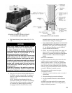
4. LOUVERS AND GRILLES of Ventilation Ducts
All outside openings should be screened and louvered.
Screens used should not be smaller than ¼ inch mesh.
Louvers will prevent the entrance of rain and snow.
a. Free area requirements need to consider the blocking
effect of louvers, grilles, or screens protecting the
openings. If the free area of the louver or grille
isnotknown,assumewoodlouvershave20-25
percent free area and metal louvers and grilles have
60-75percentfreearea.
b.Louversandgrillesmustbexedintheopen
position or interlocked with the equipment to open
automatically during equipment operation.
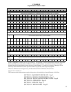
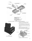
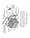
FIG. 2
SINGLE MANIFOLD BASE 5006B
THRU 5014B SECTION BOILERS
1. BASE-BURNER-MANIFOLD ASSEMBLY(S).
a.6sectionthru14sectionboilersrequiresinglebase
assembly, see Fig. 2.
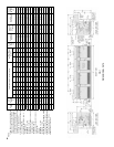
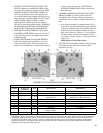
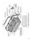
b.15sectionthru26sectionboilersrequirealeftanda
right base subassembly, see Fig. 3.
Remove Base Assembly(s) From Skid(s)
c. Remove bolts securing Base Assembly(s) to
shipping skid(s) and place Base(s) in location where
Boiler is to be installed.
d. Join Base Sub-assemblies together (15 section &
largerboilers)byrstremovinguppershipping
strip and lower shipping angles from subassemblies.
Use(4)¼”-20x¾”MS,nutsandwasherstoattach
subassemblies, see Fig. 3.
e. Attach Front Intermediate Jacket Panel Support
Bracket and Lower Rear Intermediate Panel Support
Bracket to lower channel on Front Base Frame and
RearBaseFrame,respectively,using(4)¼”-20x
¾”MS,nutsandwashers.
f. Base must be level in both directions and secure on
theoor.ShimandgroutunderBaseifnecessary.
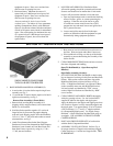
g. Place cardboard covering over the top of the burner
assembly to protect them during the assembly of the
boiler sections.
2.
CLEAN BOILER SECTIONS inside and out to remove
dirt due to shipment and handling.
Open Tie Rod Bundle(s). Open Draw-up Rod
Bundle(s).
Open Boiler Assembly Carton(s).
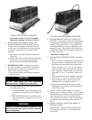
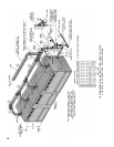
3. SET LEFT END SECTION ON BASE so that locating
lugs on bottom of section go inside Front and Rear Base
Frames. Slide section on base until these lugs strike
High Base End Panel at left end of Base, see Fig. 4.
(Note – if High Base End Panel is at right end of Base,
section assembly must start with Right End Section).
Leftendsectionsareidentiedby“LEH”caston
section;RightEndSectionsareidentiedby“REH”
cast on section.
4. CLEAN NIPPLES AND NIPPLE PORTS thoroughly
with a de-greasing solvent. Use the Loctite® #592
supplied to lubricate the nipples and nipple ports.
Apply the lubricant to the nipples and nipple ports, then
use a brush to disperse it evenly around the nipples and
thenippleports.Useapproximately25mlofLoctite®
#592perueway[(1)7”and(2)3”nipplesandtheir
(6)correspondingnippleports].UseNippleGauge
furnished – follow instructions included with gauge to
set nipples. USE ALL PRECAUTIONS TO AVOID
COCKED NIPPLES.
5. PAINT ALL GROUND SURFACES of each section
with the Sealer Compound furnished.
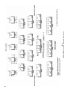
6. ASSEMBLECENTERSECTIONS.RefertoFig.6
for proper location of Tapped, and sometimes plugged,
Center Sections on 11 section and larger boilers. THIS
IS IMPORTANT.