


35
EO Control System
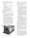
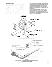
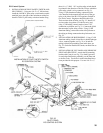
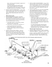
1. INSTALLATION OF PILOT SAFETY SWITCH AND
PILOTPIPING–Usingtwo#10-32x2”MSandnuts,
installtheL62GB-3Cpilotsafetyswitchbracketonthe
manifold just to the right of the main burner with pilot.
Install
L62GB-3Cpilotsafetyswitchonbracketusing
three#8x½”SMS.“IN”onpilotsafetyswitchshould
be pointed in the direction of the Gas Train to which the
pilot safety switch is to be connected, see Fig. 31.
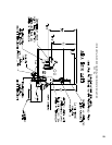
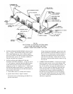
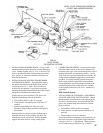
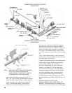
Using ¼” OD
Aluminum Tubing, connect the pilot
valve installed in the manual shut-off valve in the gas
train, to the inlet of the RV-12LT regulator (Packed in
Gas Train Carton). Regulator should be above Gas
Train and near front of boiler, see Fig. 32. Install 1/8”
tee into outlet of regulator (USA boilers only) and,
using ¼” OD tubing, connect outlet of tee to “IN”
connectiononpilotstat,seeFig.32.ConnecttheQ309
thermocouple to pilot safety switch. Using ¼” OD
aluminum tubing, connect the outlet of the pilotstat to
thetubingorttingsconnectedtothepilotburner,see
Fig. 32.
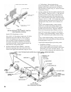
2. INSTALLATION OF BLEED PIPING – Using ¼” OD
aluminum tubing, install a bleed line on both diaphragm
valves,connecttogether,seeFig.25or26andrun
tubing to bleed line protruding from inside base, see
Fig. 32. On boiler installed in Canada, run bleed line to
outdoors.
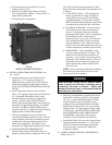
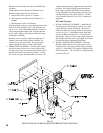
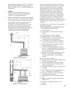
3. INSTALLATION OF “EO” PANEL AND WIRING OF
PILOT AND PILOTSTAT – Attach the EO mounting
bracket with Controls, see Fig. 33, to both Upper and
Lower Jacket End Panels, preferably on the same end
as the Gas Train. Two holes in each Jacket Panel have
beenprovidedforthispurpose.Usetwo#10-32x½”
FIG. 31
INSTALLATION OF PILOT SAFETY SWITCH
EO CONTROL SYSTEM
FIG. 32
PILOT PIPING
EO CONTROL SYSTEM