


52
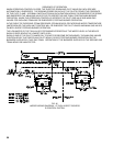
5. EOCONTROLSYSTEM–5006Bthru5014B
TheEOControlSystemutilizesanRA890F
ProtectorelayandaQ179DRecticationPilot(standing
or continuous burning pilot) to which has been added
aQ309thermocouple.TheRA890FProtectorelay
Primary Control is a non-programming, amplifying
relay which, when used with the Q179D Pilot, provides
solid state electric Flame Safeguard Protection during
a “call for heat” pilot failure. Main burners will
shutdownwithin0.8secondandtheProtectorelay
will lock out on safety shutdown within 15 seconds.
Should a pilot failure occur during the “off” cycle,
the thermocouple in the Q179D pilot will cool and,
within45to90seconds,willcausetheL62GB-3CPilot
Safety Switch to which it is connected, to break the
electrical circuit to the main gas valves, as well as shut
offtheowofgastothepilot.Thus,100%shut-offis
achieved.
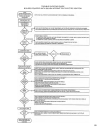
a. LIGHTING INSTRUCTIONS
(1) Make sure Manual Main Shut-off Valve and
PilotValvehavebeenoffforatleastve
minutes.
(2) Set Operating and Limit Controls to desired
setting.
(3) Turn on Main Electric Switch and Service
Switch.
(4) Turn Pilot Valve to Open Position.
(5)DepressbuttononL62GB-3CPilotSafety
Switch and hold lighted match to pilot, holding
button in for one minute or until pilot remains
lighted after button is released.
(6)PressresetbuttononRA890Frelay.
(7) Open Manual Main Shut-off Valve – main
burners will light.
Proceed to Paragraph 15- Minimum Input
Adjustments (for diaphragm “Lo-Hi-Lo” or
motorized type gas valves)
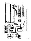
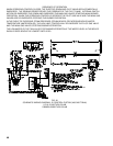
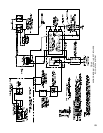
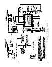
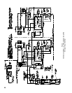
SEQUENCEOFOPERATIONEO–seeFig.46
b.NORMALOPERATION–5006Bthru5014B
(1) When the operating control calls for heat,
terminal#6ofRA890Relayisenergized.
(2)AcomponentcheckcircuitintheRA890Relay
is activated which checks the electronic network
of the relay.
(3)FlamerodcircuitoftheRA890andQ179D
provespresenceofpilotameelectronically.
(4) Terminal #5 is energized and supplies power to
the main gas valves.
(5) Main gas valves open and main burners are
lighted by pilot.
(6)Whenoperatingcontrolissatised,terminals#6
and #5 are de-energized, Main Gas Valves close
andmainburnersareextinguished.
(7) The pilot continues to burn.
c. SAFETY SHUTDOWN
(1) SAFETY SWITCH CIRCUIT
If limit control, Low
Water Cut-off or any
other electrical safety switch opens, power to
terminal#6inRelayisinterruptedthusde-
energizing terminal #5 in Relay. Main Gas
Valves are thus de-energized and main gas
burnersareimmediatelyextinguished.The
pilot will continue to burn. Normal operation
can be resumed when the cause of safety switch
malfunction is corrected. Make sure all manual
resets are activated where involved.
(2) PILOT FAILURE
(a) Flame rod supervision of pilot occurs only
during the operating cycle (call for heat) of
theoperatingcontrolsincetheRA890relay
is only energized by the operating control.
If failure occurs during this period, the main
gas valves close and the main gas burners
areextinguishedwithin0.8second.After
15 seconds the relay will lock out on safety
shutdown.
(b) If the pilot failure occurs during the “off”
cycleoftheoperatingcontrol,theRA890
relaywillnotbepoweredthruterminal#6,
therefore,thereisnoelectronicamerod
supervision. This is due to the utilization of
athermocoupleintheQ179Dmodiedpilot.
Thisthermocouplewillcoolin45to90
seconds allowing the pilot line safety valve
toclose.Thisshutsofftheowofgastothe
pilot.Itisinthismannerthat100%shut-off
is achieved. If the operating control calls for
heatduringthisperiodtheRA890relaywill
immediatelysense“noame”onpilotand
will lockout as described in paragraph (a)
above.
d. SHUTDOWN INSTRUCTIONS
(1) Close manual shut-off valve and pilot valve.
(2) Turn off main electric switch.
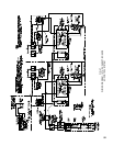
6. EOCONTROLSYSTEM5015Bthru5026B
The5015Bthru5026BboilersutilizetwoEOControl
Systems that are interconnected electrically thru all
operating and safety controls. Should any of the
aforementioned controls break the power supply circuit,
both EO control systems would be de-energized. The
succeeding paragraph describes the function and
operation of each EO Control System. Should a pilot
failure on one EO Control System occur, the other
EO Control System would not be affected. Thus
main burners on the unaffected side would ignite on a
“call for heat” and would continue to operate until the
operatingcontrolwassatised.
TheEOControlSystemutilizesanRA890F
ProtectorelayandaQ179DRecticationPilot(standing
or continuous burning pilot) to which has been added