


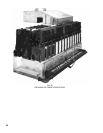

30
g. If boiler has been ordered with 3/8” try-valve
tapping, install try-cock.
h. Install “Lowest Permissible Water Level Plate”
and “Frequent Water Addition – Caution Label” on
upper left end jacket panel.
i.ProceeddirectlytoParagraph36.
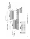
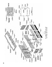
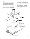
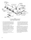
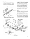
34. INSTALL WATER TRIM AND CONTROLS, see
Fig.7and26.
a. Temperature Gauge is to be installed with ½”
nippleand½”x¼”reducingcouplingin½”
tapping provided in upper corner of End Section
using wrench applied to square shank on back of
gauge. DO NOT APPLY PRESSURE ON GAUGE
GLASS.
b. Install Temperature Limit Controls as follows:
Bush 1-1/2” tapping in upper corner of End Section
to¾”andinstallTemperatureLimitControl
furnished following instructions supplied with
control. On boilers without Built-in Tankless
Heater, install second temperature limit control (not
furnished) in Tapped Heater Opening Cover Plate.
On boilers with Built-in Tankless Heater, install
operatingcontrolin¾”tappinginHeaterPlate-plug
tapping in Second Heater when supplied.
c. On boilers equipped for forced circulation hot
water heating without domestic hot water, a reverse
acting circulator control may be needed to prevent
condensationofuegasesduringperiodsoflow
boiler water temperature. This control can be
installed in the Tapped Heater Opening Cover Plate.
d. TANKLESS HEATER PERFORMANCE
Tankless heater ratings in Series 5B boilers are
basedoncontinuousdraw,temperatureriseof100ºF
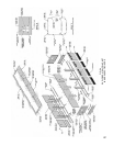
FIG. 26
WATER TRIM AND CONTROLS
(40-140ºF)andboilerwatertemperatureof200ºF.
Some of the items affecting the coil performance are
as follows:
(1)
FLOWREGULATION–Ifowthroughthe
heater is greater than its rating, the supply of
adequate hot water may not be able to keep
up with the demand. For this reason a FLOW
REGULATOR matching the heater rating should
be installed in the cold water line to the heater.
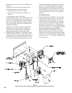
(2) FLUSHING OF HEATER - All water contains
some sediment which settles on the inside of
the coil. Consequently, the heater should be
periodically back-washed. This is accomplished
by installing hose bibs as illustrated and
allowing water at city pressure to run into hose
bib A, through the heater, and out hose bib B
until the discharge is clear. The tees in which
the hose bibs are located should be the same size
as heater connections to minimize pressure drop.
(3) HARD WATER – This is applicable to some
city water and particularly to well water. This
should not be a deterrent but precautions are
necessary. A water analysis is necessary and an
appropriate water softener installed. This is not
onlybenecialtotheheaterbuttopipingand
xturesplusthemanyotherbenetsderived
from soft water.
NOTE: A hot water boiler installed above radiation
level must be provided with a low water cut-off
device as part of the installation.
WARNING
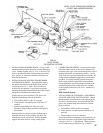
e. Following recommendations supplied with control,
install#64LowWaterCut-Offin1”pipetapping
“H” (Fig. 7) and System Return Piping. Control
must be mounted so that cut off point is above
marking on Lowest Permissible Water Line Plate.
f.
InstallPressureSafetyReliefValve,usingttings
furnished, into 1-1/2” pipe tapping in upper corner
of End Section. DO NOT INSTALL A SHUTOFF
VALVE BETWEEN SAFETY RELIEF VALVE
AND BOILER. Safety Relief Valve must be
installed in a Vertical Position with handle up.
g. Install Boiler Drain Valve into one of unused return
tappingsthathasbeenbushedto¾”.DrainValve
can also be installed in return piping, preferably
in leg of tee that is located in line with return
connection on Boiler.
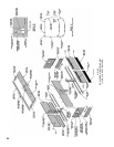
35. CONNECT PIPING TO BUILT-IN HEATER(S) IF
USED, see Fig. 27.