


46
4. EI CONTROL SYSTEM – The EI control system
utilizes a solid state ignition control which lights the
pilot burner by spark. Pilot gas is ignited and burns
during each running cycle (intermittent electric pilot).
Mainburnerandpilotgasareextinguishedduringthe
“off” cycle.
This system permits the main gas valves
[Robertshaw7000for5006Bthru5009B,(2)V88A’s
for5010Bthru5014B]toopen,andthepilotlinegas
valve to remain open, only when the Pilot Burner is
proven to be lit.
Shouldalossofameoccur,themainvalvecloses
andthesparkreoccurswithin0.8second.Theignition
modulehasaninternal100%lockoutfunctionto
completely shutdown the system should the pilot gas
failtoignitewithinapproximately90seconds.Fiveto
sixminutesaftershutdown,theIgnitionModulerestarts
the ignition sequence. The ignition trial, shutdown, and
wait sequence continues until either the pilot lights or
the Thermostat is set below room temperature (to end
the call for heat). The ignition sequence can be reset by
setting down the Thermostat for one minute.
a. OPERATING INSTRUCTIONS
(1) Make sure all Manual Main Shut-off Valves and
allPilotValveshavebeenoffforatleastve
minutes.
(2) Set Operating and Limit Controls to desired
settings.
(3) Turn all Manual Main Shut-Off Valves and Pilot
Valves to Open Position.
(4) Turn on Main Electric Switch and Service
Switch – Pilot(s) will automatically light main
burners.
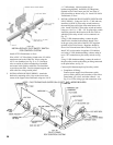
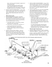
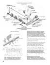
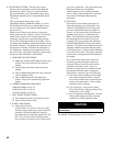
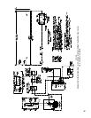
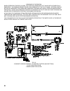
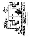
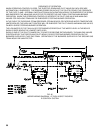
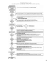
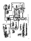
b. NORMAL OPERATION SEQUENCE
5006Bthru5009B,seeFig.42
5010Bthru5014B,seeFig.43
5015Bthru5026B,seeFig.44
c. SHUT DOWN INSTRUCTIONS
(1) Close manual shut-off valves and pilot valves.
(2) Turn off main electric switch.
d. SAFETY SHUTDOWN
(1) Safety Switch Circuit
If limit control, low water cut-off or any other
electrical safety switch opens, power to the 24V
terminalofallS8610MIgnitionControlsis
interrupted thus de-energizing terminals PV and
MV. Loss of power to these terminals means
loss of power to all pilot gas valves and to main
gas valves, respectively. Thus, pilot burner and
main
burneramesareextinguished.
Normal operation can be resumed when the
cause of safety switch malfunction is corrected.
Any controls with Manual Reset must be
reactivated.
(2) Pilot Failure
Pilot failure can occur during the start-up or
during the operating cycle of the boiler. Any
failure of a Q3481B pilot will close the main
gasvalvescontrolledbythispilotwithin0.8
second.For90secondsafterpilotfailure,the
Ignition Control will try to reestablish pilot
ame.Ifthepilotamecannotbesensedby
the sensing probe, the module will lock out
onsafety.Fivetosixminutesaftershutdown,
the IGNITION MODULE restarts the ignition
sequence. The ignition trial, shutdown, and wait
sequence continues until either the pilot lights
or the Thermostat is set below room temperature
(to end the call for heat). The ignition sequence
can be reset by setting down the Thermostat for
one minute.
On 15 section and larger boilers, where two
manifolds, gas trains and pilot systems are
employed, failure of one pilot will not affect
operation of the other system. Thus, it is
possibletoretheboileratareducedratethru
one manifold while the other is inoperative.
Pilot failure is caused by one of the following:
(a) Pilot burns yellow resulting in weak signal
from sensor to Ignition Control – may be
due to dirt or lint that has covered the lower
portion of the pilot burner – remove with a
soft brush or by vacuuming.
(b) Loss of pilot gas – may be due to faulty
pilot solenoid valve, improper wiring, loose
connections, or low voltage.
(c) Loss of signal from sensing probe – may be
faulty probe, improper or loose electrical
connection, or faulty Ignition Control.
CAUTION
connections.
ForS8610MTroubleShootingGuide,seePage51.