


33
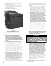
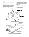
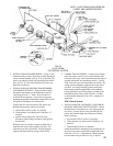
FIG. 28
INSTALLATION OF S8610M MODULE
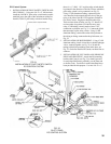
EI Control System
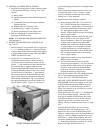
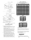
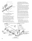
1. INSTALLATION OF GAS VALVE TRANSFORMER
AND PILOT PIPING (for Robertshaw Pilot Piping,
see Fig. 29) – Attach the bracket for mounting of the
junctionboxtothelowerfrontcorneroftheJacket
UpperEndPanelusingtwo#10-32x½”MSandnuts.
Mountjunctionboxtobracketusing#8SMS,seeFig.
25or26.Connectpilotsolenoidvalvetobottomcenter
knockoutofJ-boxusingconduitttingsfurnished,
(V88GasTrainonly)seeFig.30.Mounttransformer
onJ-box.IfFootMountedTransformer,connectto
J-boxwithStraightConnector,BX,StraightConnector
and ½” pipe coupling. Drill holes in Jacket and fasten
Transformer using SMS. Install RV-12LT pilot line
regulator (packed in Gas Train Carton) and other 1/8”
pipe
ttingsasshowninSectionVI,RepairParts(V88
Gas Train only).
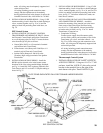
Using ¼” OD aluminum tubing, connect the inlet of
the pilot solenoid valve to the pilot valve installed in
the manual shut off valve in the Gas Train. Using ¼”
aluminum tubing, complete installation to Pilot Burner,
seeFig.30(V88GasTrainonly).
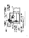
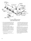
FIG. 29
PILOT PIPING - EI CONTROL SYSTEM (Robertshaw7000)
U.S.A. 5006B THRU 5009B