


75
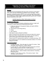
1. GENERAL – “Inspection should be conducted
annually.Serviceasfrequentlyasspeciedin
paragraphs below.” While service or maintenance is
being done, Electrical Power and all Gas Supply to the
Boiler must be “off”.
CAUTION
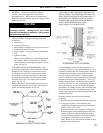
2. VENT SYSTEM – Vent system should be checked
annually for:
a.
obstructions
b. accumulations of soot
c. deterioration of vent pipe or vent accessories due to
condensation or other reasons
d. proper support – no sags, particularly in horizontal
runs
e. tightness of joints
Remove all accumulations of soot with wire brush
and vacuum. Remove all obstructions. Replace
all deteriorated parts and support properly. Seal all
joints.
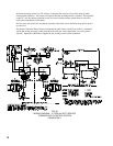
SeeFig.61.
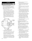
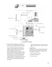
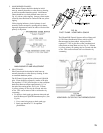
3. CLEANING OF FLUES AND BURNERS – Flue
passageways in the boiler sections should be checked
annually for any blockage or accumulation of soot.
T
oobtainaccesstotheuecleanoutpanels,which
are installed on both the front and rear of the boiler,
the upper front and upper rear jacket panels must be
removed, see Fig. 59. Also remove front vestibule
panel. See Fig. 18.
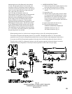
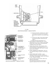
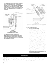
RemovetheFrontCleanoutPanelsrstbyremoving
the upper and lower nuts and washers securing these
panelstotheboilersections,seeFig.60.
SECTION V – SERVICE
CARE SHOULD BE EXERCISED IN REMOVING
THE CLEANOUT PLATES FROM THE BOLTS SO
THAT THE INSULATION IS NOT DAMAGED. IF
DAMAGED, ALL EDGES OF THE CLEANOUT
PLATES SHOULD BE SEALED WITH BOILER
PUTTY WHEN REINSTALLED UNTIL
INSULATION CAN BE REPLACED.
FIG. 60
ATTACHMENT OF FLUE COVERS
Usingaashlight,examinealluepassageways.If
passageways are free of soot and obstructions, it is not
necessary to remove the rear cleanout panels. Remove
the Burner Access Panels at front of base and place
paper or cardboard over burners. With long handle
wireuebrushandvacuum,brushuewaysthoroughly
throughfrontandrearcleanoutopenings–seeFig.61.
Remove material placed over burners and vacuum the
following with care so as not to disturb base insulation:
oor,topofburners,primaryairopeninginburners,
and primary air openings in pilot. This will remove any
dust or lint that may have accumulated as well as any
foreign matter that may have been dislodged during the
cleaningoftheues.
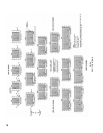
If Burners must be removed, use the following
procedure:
a. Mark location on manifold of all burners with pilots.
b. Using a pair of pliers, remove hitch pin clips
(shaped like a hairpin) from groove in main burner
orices.SAVEALLCLIPS.
c. Remove all burners without pilots by lifting front
of burner slightly, then pushing burner toward rear
ofboileruntilfrontofburnerclearsorice,then
lift rear of burner until head of weld pin on bottom
rear of burner clears keyhole slot in base rear
panel. Burner is now free and can be lifted out thru
opening in base front frame.
FIG. 59
REMOVAL OF JACKET FRONT PANEL