


32
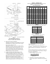
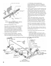
3/4” - 2.1 ft. 2” - 5.2 ft.
1” - 2.6 ft. 2-1/2” - 6.2 ft.
1-1/4” - 3.5 ft. 3” - 7.7 ft.
1-1/2” - 4.0 ft. 4” - 10.1 ft.
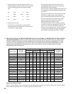
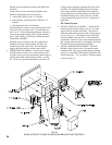
38. THE INSTALLATION OF THE REMAINDER OF THE GAS CONTROLS IS DEPENDENT ON THE CONTROL
SYSTEM FURNISHED. REFER TO THE TABLE BELOW FOR THE FIGURES IN THIS MANUAL APPLICABLE
TO THE VARIOUS CONTROL SYSTEMS OFFERED AS STANDARD OR AS OPTIONAL EQUIPMENT. IF THE
CONTROL SYSTEM ORDERED IS NOT LISTED, SPECIAL INSTRUCTIONS HAVE BEEN PREPARED BY THE
APPLICATION ENGINEERING DEPARTMENT AND CAN BE FOUND IN THE INSTRUCTION ENVELOPE
FURNISHED WITH THE BOILER.
BOILER SIZE
CONTROL
SYSTEM
NATURAL GAS LP
REFERENCE
FIGURES
USA CANADA USA CANADA
STD OPT STD OPT STD OPT STD OPT
6 thru 9 sect. EI X --- --- X X --- --- --- 28, 29
10 thru 26 sect. EI X --- --- X --- --- --- --- 28, 30
6 thru 26 sect. EI --- X --- --- --- --- 28, 30
6 thru 9 sect. EO --- X --- X --- X X --- 31, 32, 33
10 thru 13 sect. EO --- X --- X X --- X --- 31, 32, 33
14 sect. EO --- X X --- X --- X --- 31, 32, 33
15 thru 24 sect. EO --- X --- X X --- X --- 31, 32, 33
26 sect. EO --- X X --- X --- X --- 31, 32, 33
6 thru 14 sect. EE --- X --- X --- --- --- --- 33, 34
15 thru 26 sect. EE --- X --- X --- --- --- --- 33, 34
6 thru 14 sect. EOP --- X --- --- --- X --- --- 35, 36
15 thru 26 sect. EOP --- X --- --- --- X --- --- 35, 36
6 thru 14 sect. EEP --- X --- --- --- --- --- --- 37
15 thru 26 sect. EEP --- X --- --- --- --- --- --- 37
6 thru 13 sect. Thermocouple --- --- X --- --- --- --- --- 38
15 thru 24 sect. Thermocouple --- --- X --- --- --- --- --- 39
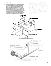
Open Gas Controls Carton(s)
NOTE: On those boilers with two manifolds (15 sect. and larger), two identical sets of Gas Controls are furnished. Hence,
the procedure for installing one set is equally applicable to the second set.
c. Length of piping in feet and number of elbows – for
practicalpurposeseach90ºelbowcanbeconsidered
as the following equivalent in length of straight
pipe:
d.Specicgravityofgas
In the absence of requirements of the authority
having jurisdiction, the tables below may be used to
size natural gas supply piping.
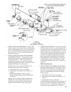
A pipe thread compound resistant to the action
ofliqueedpetroleumgasesmustbeusedonall
threaded joints in the gas piping.
Pressure testing of the Gas Supply Piping Boiler and
its connections is required before placing the boiler
in operation.
The boiler and shutoff valve must be disconnected
from the gas supply piping system during any
pressure testing at pressures greater than ½” psig.
The boiler must be isolated from the gas supply
piping system during any pressure testing at
pressures equal to or less than ½ psig.
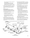
WITH GAS SUPPLY “OFF” and Service Piping
connected to the boiler, open Manual Valve(s) and
pilot valve(s) at end of Gas Train(s) and reduce
pressure to ½ lb. gage pressure. Using soap solution
or other approved method check gas train piping,
pilotpiping,bleedpipingandoricesforleaks.