


61
(6)AdefectiveRA890maybethecause
but items (1) thru (5) should be followed
rst.ReferalsotoRA890relayliterature
furnished with the control.
(d) By referring to the Sequence of Operations
step by step operation of the system can
be controlled and the cause of pilot failure
can be readily found. After the cause of
pilot failure has been corrected, resume
normal operation by following the Lighting
Instructions.
d. SHUTDOWN INSTRUCTIONS
(1) Close manual shut-off valves and pilot valves.
(2) Turn off main electric switch.
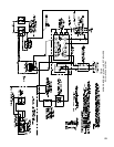
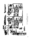
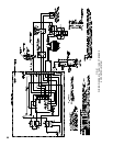
9. EOPCONTROLSYSTEM–5006Bthru5014B
The EOP Control System functionally is the same as
theEOControlSystem.TheRA890FProtectorelay,
however, is installed in a prewired control cabinet along
with a terminal strip, “main power” switch, “main gas
valves” switch, “main power” lamp, “main gas valves”
lamp and “pilot failure” lamp.
TheRA890FProtectorelayPrimaryControlisanon-
programming, amplifying relay which, when used with
the
Q179DRecticationPilot(standingorcontinuous
burning pilot), provides solid state electric Flame
Safeguard Protection during a “call for heat” pilot
failure. Should this occur, main burners will shut down
within0.8second,“MainGasValvesLamp”willgo
off, the Protectorelay will lock out on safety shutdown
within 15 seconds, and the “Pilot Failure Alarm Lamp”
will be lighted. The thermocouple in the Q179D pilot
willcooland,within45to90seconds,willcausethe
L62GB-3CPilotSafetySwitchtowhichitisconnected
to break the electrical circuit to the main gas valves as
wellasshuttingofftheowofgastothepilot.Thus
100%shut-offisachieved.
Should a pilot failure occur during the “off” cycle,
the thermocouple in the Q179D pilot will cool and,
as described above, will shut off main gas valves
and
owofgastopilot.Onthenextcallforheatthe
Protectorelay will immediately sense the absence of
pilotameandthe“PilotFailureAlarmLamp”willbe
lighted.
a. LIGHTING INSTRUCTIONS
(1) Turn off all panel switches.
(2) Turn off manual main and pilot gas valve. Wait
atleastve(5)minutesbeforeproceeding.
(3) Push safety switch reset button on this panel.
(4) Turn on manual pilot gas valve. Push and hold
pilot safety valve button and light pilot. When
pilot is lit, proceed.
(5)
Set operating control to desired temperature or
pressure.
(6)TurnonMain Power Switch. Main Power Light
will light.
(7) Turn on manual main gas valve.
(8) Turn on Main Gas Valve Switch to light main
burners. Main Gas Valve Light will light.
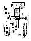
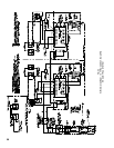
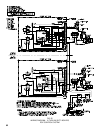
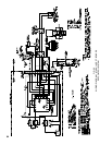
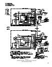
SEQUENCE OF OPERATION EOP – See Fig. 51
b.NORMALOPERATION–5006Bthru5014B
(1) When the operating control calls for heat,
terminals#6ofPanelandRA890Relayare
energized.
(2)AcomponentselfcheckcircuitintheRA890
Relay is activated which checks the electronic
network of the relay.
(3)FlamerodcircuitoftheRA890andQ179D
provespresenceofpilotameelectronically.
(4) Terminal #5 is energized and supplies power to
the main gas valves and main gas valve panel
light providing “Gas Valve On Switch” is
closed.
(5) Main gas valves open and main burners are
lighted by pilot. “Main Gas Valve” lamp will be
activated.
(6)Whenoperatingcontrolissatised,terminals
#6and#5arede-energized,“MainGasValve”
light goes out, Main Gas Valves close, and main
burnersareextinguished.“MainGasValve”
lamp will go dark.
(7) Pilot continues to burn.
(8) “Main Power” lamp will remain lighted.
c. SAFETY SHUTDOWN
1. SAFETY SWITCH CIRCUIT
If limit control, Low Water Cut-Off or any other
electrical safety switch opens, power to terminal
#6inPanelisinterruptedde-energizingterminal
#5 in Panel. Main Gas Valves are thus de-
energized and main gas burners are immediately
extinguished.Thepilotwillcontinuetoburn.
Normal operation can be resumed when the
cause of safety switch function is corrected.
Make sure all manual resets are activated where
involved.
2. PILOT FAILURE
(a) Flame rod supervision of pilot occurs only
during the operating cycle (call for heat)
oftheoperatingcontrolsincetheRA890
relay is energized by the operating control.
If pilot failure occurs during this period,
the main gas valves close and the main gas
burnersareextinguishedwithin0.8second.
After 15 seconds the relay will lock out
on safety shutdown and the “Pilot Failure
Alarm Lamp” will be lighted.
(b) If pilot failure occurs during the “off”
cycleoftheoperatingcontrol,theRA890F
relaywillnotbepoweredthruterminal#6,
therefore,thereisnoelectronicamerod
supervision. This is due to the utilization of
athermocoupleintheQ179Dmodiedpilot.