


25
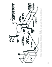
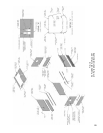
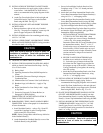
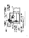
22. INSTALLATION OF TOP FRONT JACKET PANEL
a. Remove knockout for supply piping (right or left for
water boilers – both knockouts for steam boilers)
refer to recommended boiler piping diagrams in this
manual.
b. Attach Top Front Jacket Panel to left and right end
Jacket Panel and to Top Flange on the Vestibule
Panel using #8 SMS. See Fig. 22.
23.
INSTALLATION OF LEFT AND RIGHT TOP SIDE
JACKET PANEL
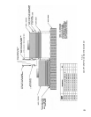
a. Remove knockout, right or left, only if needed.
(See Fig. 7 for purpose of tappings), secure top side
panels to upper end panels with #8 SMS.
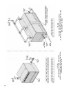
24. INSTALL KNOBS on the four remaining panels using
#10-32x3/16”MS.
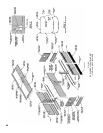
25. INSTALL UPPER FRONT, LOWER FRONT, UPPER
REAR AND LOWER REAR PANELS using procedure
described in detail “A” of Fig. 23.
CAUTION
combustion air.
26. T
IGHTEN ALL SHEET METAL SCREWS.
27. INSTALL THE FOLLOWING PLATES OR LABELS
which are found in the Instruction Envelope. See Fig.
19 or 22 for location.
(1) Rating Label
(2) Operating Instruction Plate (#8 SMS required to
fasten)
(3) Combustible Clearance Flooring & Adequate
Combustion Plate
(4) Minimum Service Clearance Label (self-adhesive)
(5) Burnham Logo (self-adhesive) – Apply to Top
Panel
(6)BoilerVentilationForYourSafetyLabel–Apply
to Top Panel
(7) Proceed to Paragraph 33 (Steam Boilers) or
Paragraph 34 (Water Boilers).
COMPLETION OF JACKET INSTALLATION 11
THRU26SECTIONBOILERS.
28. PARAGRAPHS 1 THRU 4 HAVE ALREADY BEEN
COMPLETED.RefertoParagraph16forinstallation
of lower framework.
a. Install Vestibule Panel(s) – refer to Fig. 19 and 22.
AttachHexCouplingstoendofCarriageBolts
which secure Flue Cover Plates.
NOTE: Select Carriage Bolts which line up with holes
in the Vestibule Panel(s).
b. Attach Intermediate Vestibule Panel(s) to one of the
Vestibule Panel(s) using #8 SMS.
c. SecureLeftandRightVestibulePanelstoHex
Couplingsusing¼”-20x3/8”slottedpanhead
machine screws.
d.
Attach the Lower Rear Intermediate Panels to the
Lower Rear Intermediate Panel Support Bracket(s)
using#10-32x½”selftappingscrews.
e. Attach the Upper Rear Intermediate Panel(s) to the
Lower Rear Intermediate Panel(s) using #8 SMS.
f. Attach Rear Top Intermediate Jacket Panel(s) to Rear
Top Left and Right Jacket Panels using #8 SMS.
g. Place Assembled Rear Top Jacket Panel in position
and attach to Upper End Panels and Upper Rear
Intermediate Panel using #8 SMS.
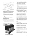
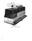
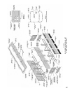
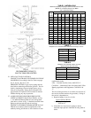
a. INSTALLATION OF CANOPY-DRAFTHOOD
11THRU26SECTIONBOILERS–these
boilers require two or more Canopy-Drafthoods
–refertoFig.6forproperarrangement.
Determine where ends of Canopy-Drafthood rest
onintermediatesections.Place1”x14-1/2”
Cerafelt strips on top of intermediate section at
these locations. Place Cerafelt strips on top of
sectionassemblynexttoledgesformedbycenter
sectionsandnexttoledgesonendsections.
Overlap at corner.
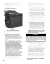
b. SECURE CANOPY-DRAFTHOODS with
machine screws and bolts as shown in Fig.
21. Select the type of fastener indicated and
drive them into the Tapped Lugs provided for
this purpose on top of the sections. Where two
Canopy-Drafthoods join together, the securing
tabs will overlap.
c. Attach the Front Intermediate Panel to the Front
Intermediate Panel Support Bracket(s), using
#10-32x½”selftappingscrews.
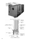
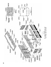
29. INSTALLATION OF TOP FRONT JACKET PANELS
a. Remove knockout for supply piping. Refer to
recommended boiler piping diagrams in this manual.
b. Attach Top Front Jacket Panels to left and right end
JacketPanelsandalsototopangeontheVestibule
Panel using #8 SMS. Refer to Fig. 23 or 24.
30. P
LACE TOP INTERMEDIATE PANEL(S) ON TOP
OF LEFT AND RIGHT PANELS, making sure that
Front Intermediate Panel(s) is under Top Intermediate
Panel(s). Secure Top Intermediate Panel using #8 SMS.
31. INSTALL KNOBS ON THE UPPER FRONT AND
UPPER REAR PANELSusing#10-32x3/16”MS.
Install Upper Front, Lower Front, Upper Rear and
Lower Rear Panels using procedure we described in
detail “A” of Fig. 23 or 24.
CAUTION
combustion air.