


54
toaQ309Thermocouple.TheRA890FProtectorelay
Primary Control is a non-programming, amplifying
relay which when used with the Q179D Pilot provides
solid state electronic Flame Safeguard Protection
during a “call for heat” pilot failure. Main burners
willshutdownwithin0.8secondandtheProtectorelay
will lock out on safety shutdown within 15 seconds.
Should a pilot failure occur during the “off” cycle, the
thermocouplewillcoolandwithin45to90seconds,
willcausetheL62GB-3CPilotSafetySwitchtowhich
it is connected, to break the electrical circuit to the main
gasvalvesaswellasshutofftheowofgastothe
pilot.Thus100%shut-offisachieved.
a. LIGHTING INSTRUCTIONS
(1) Make sure all Manual Main Shut-off Valves and
allPilotValveshavebeenoffforatleastve
minutes.
(2)
Set Operating and Limit Controls to desired
settings.
(3) Turn on Main Electric Switch and Service
Switch.
(4) Open pilot valve on one side of boiler. Depress
buttononL62GB-3CPilotSafetySwitchto
which it is connected and light pilot with match.
Continue to hold button in for one minute
or until pilot remains lighted after button is
released. Light pilot on opposite side of boiler
using same procedure.
(5)PressresetbuttononeachRA890Frelay.
(6)OpenManualMainShut-offValves–main
burners will light.
Proceed to Paragraph 15- Minimum Input
Adjustments (for diaphragm “Lo-Hi-Lo” or
motorized type gas valves)
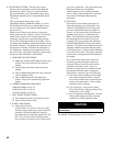
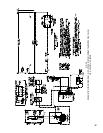
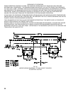
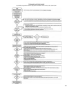
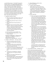
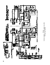
SEQUENCE OF OPERATION EO – See Fig. 47
b.NORMALOPERATION–5015Bthru5026B
(1) When the operating control calls for heat,
terminal#6ofeachRA890FProtectorelayis
energized.
(2)AcomponentcheckcircuitineachRA890
Protectorelay is activated which checks the
electronic network of the relay.
(3) Flame rod circuit between each Q179D pilot and
terminal“F”onitsrespectiveRA890Fproves
presenceofameelectronicallyatitsQ179D
pilot.
(4)Terminal#6oneachRA890Fisenergized
supplying power to its respective main gas
valves.
(5) Main gas valves open and main burners are
ignitedbythepilotames.
(6)Whenoperatingcontrolissatised,terminals#6
and#5ontheRA890Frelaysarede-energized,
main gas valves close and main burners are
extinguished.
(7) The Q179D pilots continue to burn.
c. SAFETY SHUTDOWN
(1) SAFETY SWITCH CIRCUIT
If limit control, low water cut-off or any
other electrical safety switch opens, power
to
terminal#6andallotherterminalsonboth
RA890Frelaysisinterrupted.Maingasvalves
are thus de-energized and main gas burners
areimmediatelyextinguished.Standingpilot
amesintheQ179Dpilotswillcontinueto
burn.
(2) PILOT FAILURE
(a) Flame rod supervision of the Q179D pilots
occurs only during the operating cycle (call
for heat) since it is during this period that
thecontrolisenergizingtheRA890Frelays.
If pilot failure occurs during this period
on one of the Q179D pilots, the main gas
valvescontrolledbythatparticularRA890F
willclosein0.8second.TheRA890Fwill
lock-out on safety within 15 seconds. The
burnerscontrolledbytheotherRA890Fwill
continue to burn.
(b) If pilot failure occurs on one of the Q179D
pilots during the “off” cycle of the operating
control,therewillbenoelectronicamerod
supervisionsinceneitherRA890Frelayis
energized during the off cycle. This is due
to the utilization of a thermocouple in each
Q179Dmodiedpilotwhichcontrolsits
own pilot safety switch. This thermocouple
willcoolin45to90secondsde-energizing
the pilot safety switch which interrupts the
circuit between terminal #5 and the gas
valvesandalsoshutsofftheowofgasto
thepilot.Thus100%shut-offisachieved.
If the operating control calls for heat
duringthisperiodtheRA890Frelaywill
immediatelysense“noame”onthepilot
and the relay will lock out on safety within
15 seconds.
Assuming the pilot on the opposite side is
burning, the gas valves on that side will
openandmainamewillbeignitedonthat
side only.
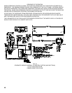
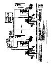
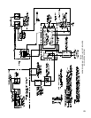
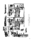
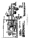
7. EECONTROLSYSTEM–5006Bthru5014B
TheEEControlSystemutilizesanRA890F
ProtectorelayandaQ179CRecticationPilot,which
inadditiontoapilotburnerandrectifyingamerod
amedetectortoprovepilot,includesanignition
electrode for spark ignition of the pilot. A Webster
612-6A7Transformersuppliesthehighvoltagespark
potential.Oncepilotameisproven,ignitionstopsbut
pilotamecontinuesaslongasthereisa“callforheat”
(intermittent electrically ignited pilot).
TheRA890FProtectorelayPrimaryControlisanon-
programming amplifying relay which when used with