


63
Thisthermocouplewillcoolin45to90
seconds allowing the pilot line safety valve
toclose.Thisshutsofftheowofgastothe
pilot.Itisinthismannerthat100%shut-off
is achieved. If the operating control calls for
heat during this period and the “Power On”
switch is still in the “ON” position this relay
will automatically sense the absence of pilot
ameandthe“PilotFailureAlarmLamp”
will be activated as described in paragraph
(a) above.
d. SHUTDOWN INSTRUCTIONS
(1) Turn off all switches on panel(s).
(2) Turn off manual main and pilot shut-off valves.
10.EOPCONTROLSYSTEM–5015Bthru5026B
The5015Bthru5026BboilersutilizetwoEOPControl
Systems that are interconnected electrically thru all
operating and safety controls. Should any of the
aforementioned controls break the power supply circuit,
both EOP Control Systems would be de-energized.
The succeeding paragraphs describe the function and
operation of each EOP Control System. Should a pilot
failure on one EOP Control System occur, the other
EOP Control System would not be affected. Thus
main burners on the unaffected side would ignite on a
“call for heat” and would continue to operate until the
operatingcontrolwassatised.
The EOP Control System functionally is the same as
theEOControlSystem.TheRA890FProtectorelay,
however, is installed in a prewired control cabinet along
with a terminal strip, “main power” switch, “main gas
valves” switch, “main power” lamp, “main gas valves”
lamp and “pilot failure” lamp.
TheRA890FProtectorelayPrimaryControlisanon-
programming amplifying relay which, when used with
theQ179DRecticationPilot(standingorcontinuous
burning pilot) provides solid state electronic Flame
Safeguard Protection during a “call for heat” pilot
failure. Should this occur, main burners will shut down
within0.8second,“MainGasValvesLamp”willgo
off, the Protectorelay will lockout on safety shutdown
within 15 seconds and the “Pilot Failure Alarm Lamp”
will be lighted. The thermocouple in the Q179D pilot
willcooland,within45to90seconds,willcause
theL62GB-3CPilotSafetySwitchtowhichitin
connected, to break the electrical circuit to the main
gasvalvesaswellasshuttingofftheowofgastothe
pilot.Thus100%shut-offisachieved.
OnthenextcallforheattheProtectorelaywill
immediatelysensetheabsenceofpilotameandthe
“Pilot Failure Alarm Lamp” will be lighted.
a. LIGHTING INSTRUCTIONS
(1) Turn off all switches on both panels.
(2) Turn off all manual main and pilot gas valves.
Waitatleastve(5)minutesbeforeproceeding.
(3) Push safety switch reset button on both panels.
(4) Turn on one pilot gas valve. Depress button on
L62GB-3CPilotSafetySwitchtowhichitis
connected and light pilot with match. Continue
to hold button in for one minute or until pilot
remains lighted after button is released. Light
second pilot using same procedure.
(5) Set operating control to desired temperature or
pressure.
(6)TurnonMainPowerSwitch.MainPower
Lamps will light.
(7) Turn on Manual Main Gas Valves.
(8) Turn on Main Gas Valve Switch on both panels
to light burners. Main Gas Valve Light on each
panel will light.
Proceed To Paragraph 15- Minimum Input
Adjustments (for diaphragm “Lo-Hi-Lo” or
motorized type gas valves)
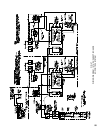
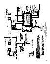
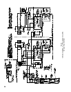
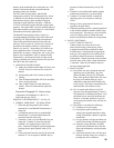
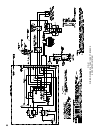
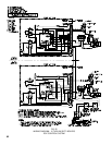
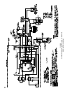
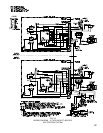
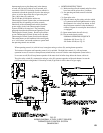
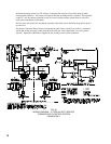
SEQUENCE OF OPERATION EOP – See Fig. 52
b.NORMALOPERATION–5015Bthru5026B
(1) When the operating control calls for heat,
terminal,#6terminalofeachRA890F
Protectorelayisenergizedthroughterminals1,6
& 7 of their respective panel terminal strip.
(2)Acomponentself-checkcircuitineachRA890F
relay is activated which checks the electronic
network of the relay.
(3)FlamerodcircuitofeachRA890Frelayandits
Q179Dpilotprovesthepresenceofpilotame
electronically.
(4)Terminal#5oneachRA890Fisenergized,and
providing the “Main Gas Valve Switch” is “ON”
(circuit closed), supplies power to its respective
main gas valves.
(5) “Main Gas Valve” lamps will be lighted, main
gas valves will open and main burners will be
ignitedbythepilotames.
(6)Whenoperatingcontrolissatised,terminals#6
and#5ontheRA890Frelaysarede-energized,
main gas valves close and main burners are
extinguished.“MainGasValve”lampswillgo
off.
(7) The Q179D pilots continue to burn.
c. SAFETY SHUTDOWN
(1) SAFETY SWITCH CIRCUIT
If limit control, Low Water Cut-off, operating
control or any other electrical safety switch in the
limit circuit opens, power to terminal #1 on both
panels is interrupted, de-energizing both control
panels causing all main gas valves on both sides
to close and main gas burners are immediately
extinguished.Bothpilotswillcontinuetoburn.
Normal operation can be resumed when the
cause of the safety switch action is corrected.
Make sure all manual resets are activated where
involved.