


38
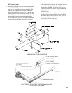
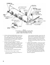
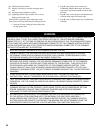
FIG. 35
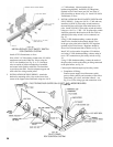
INSTALLATION OF PILOT SAFETY SWITCH
EOP CONTROL SYSTEM
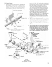
x½”MSandnuts.Mountjunctionboxto
bracket using #8 SMS. Install RV-12LT Regulator,
(Packed in Gas Train Carton) and 1/8” tee in the ¼”
ODpilottubingasshowninFig.36.Install24V/40VA
TransformeronJ-box.
3. INSTALLATION OF PILOT SAFETY SWITCH AND
PILOTPIPING–Usingtwo#10-32x2”MSandnuts,
installtheL62GB-3Cpilotsafetyswitchbracketon
the manifold just to the right of the main burner with
pilot.InstallL62GB-3Cpilotsafetyswitchonbracket
usingtwo#10-32x½”MS.“IN”onpilotsafetyswitch
should be pointed in the direction of the Gas Train to
which the pilot safety switch is to be connected, see
Fig. 35.
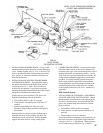
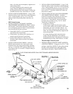
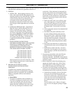
Using ¼” OD aluminum tubing, connect the pilot
shutoff valve installed in the manual shutoff valve
in the gas train, to the inlet of the RV-12LT regulator
(packed in Gas Train Carton). Regulator should be
aboveGasTrainandnearfrontofboiler,seeFig.36.
Install 3/8” tee into outlet of regulator (USA boilers)
and, using ¼” OD aluminum tubing, connect outlet of
tee to “IN” connection on pilot safety switch, see Fig.
36.
Using ¼” OD aluminum tubing, connect the outlet of
thepilotsafetyswitchtothetubingorttingconnected
tothepilotburner,seeFig.36.
ConnectQ309thermocoupletopilotsafetyswitch.
a. Completion of Wiring -
Connect power supply fused disconnect switch
service switch, primary and secondary of Gas Valve
Transformer, gas valves, and other controls – see
Fig. 51 or 52 for wiring type and connections to be
FIG. 36
PILOT PIPING
EOP CONTROL SYSTEM
NOTE - PILOT PIPING DUPLICATED ON 15 SECT. AND LARGER BOILERS.
InstallAT72DTransformeronJ-box.
WireL62G13-3CPilotSafetySwitchtothe24V/40VA
transformer and to the V88A Gas Valves using the
105ºC
wirefurnished,seeFig.51or52.Runthese
wires to outside of jacket on underside of manifold
and secure in this position with Wire Ties furnished
to provide strain relief. Provide adequate support and
strain relief for wiring outside jacket.
2. INSTALLATION OF PILOT PIPING – Attach the
bracketformountingoftheJ-boxtothelowerfront
corneroftheUpperJacketEndPanelusingtwo#10-32