


34
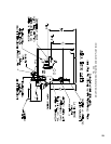
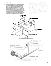
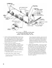
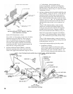
FIG. 30
PILOT PIPING - EI CONTROL SYSTEM (V88A)
U.S.A. 5010B THRU 5026B - NAT. GAS
CANADA - 5006B THRU 5026B - NAT. GAS
2. INSTALLATION OF BLEED PIPING (V88 Gas Train
only) – Using ¼” OD aluminum tubing, install a bleed
line on both diaphragm gas valves, connect together,
and, on USA boilers, run tubing to bleed line protruding
from
insidebase,seeFig.30.Onboilersinstalledin
Canada, run bleed line to outdoors.
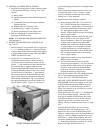
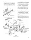
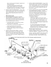
3. INSTALLATIONANDWIRINGOFS8610M
IGNITIONCONTROLMODULE–Usingtwo#10-32
x2”MS,andnuts,installtheS8610Mmodulebracket
on the manifold just to the right of the main burner
withpilot,seeFig.28.Usingtwo#6x¾”SMS,install
theS8610Mmoduleonthebracket.Connectthetwo
wiresfromtheQ3481BpilottotheS8610Mmoduleas
shown on Fig. 42, 43 or 44.
a.GroundWire(200ºC)to“BNRGND”terminal
b. Ignition Sensor Wire to “Spark” terminal
Secure these wires to Pilot Piping with Wire Tie to
provide strain relief.
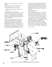
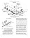
Using wiring harness furnished, connect leads with
push-onterminalsonS8610Mmoduleasshownin
Fig. 42, 43 or 44. Run harness outside of jacket on
underside of manifold and secure in this position
withWireTiesfurnished.Connectthesixwiresin
theharnesstothespeciedcontrolsasshowninFig.
42, 43 or 44.
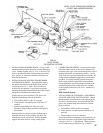
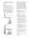
4. COMPLETION OF WIRING – Connect power supply
fused disconnect switch, service switch, primary side
of transformer, gas valves and remaining controls – see
Fig. 42, 43 or 44 for wire type and connections to be
made. All wiring must be adequately supported and
strain relief provided. All wiring including ground
connections must comply with the requirements of
the authority having jurisdiction and, in the absence
of such, to the National Electrical Code, ANSI NFPA
No.70-2005,ortheCanadianElectricalCode,C22.1,
whichever is applicable.