


56
the Q179C Pilot provides solid state electronic Flame
Safeguard Protection that will not allow the main gas
valves to open on “call for heat” for that will shut
downmainburnerswithin0.8secondifpilotame
is not “proved”. Protectorelay will lockout on safety
shutdownwithin15secondsifthereisapilotame
failure on start or, if during the “run” cycle, pilot
ameisnotre-established.Since#3terminalinthe
Protectorelay is de-energized at end of safety switch
timing, a solenoid valve in the pilot line will close and
thus100%shut-offisachieved.
a. OPERATING INSTRUCTIONS
(1) Make sure Manual Main Shut-off Valve and
allPilotValvehavebeenoffforatleastve
minutes.
(2) Set Operating and Limit Controls to desired
settings.
(3) Turn Manual Main Shut-off Valve and Pilot
Valve to Open Position.
(4) Turn on Main Electric Switch and Service
Switch – Pilot will automatically light main
burners.
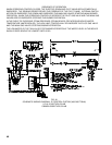
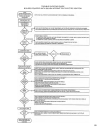
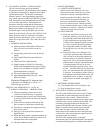
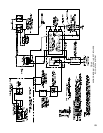
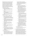
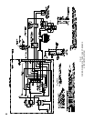
SEQUENCE OF OPERATION EE - See Fig. 48
b.NORMALOPERATION-5006Bthru5014B
(1) When the operating control calls for heat,
terminal#6ofRA890Relayisenergized.
(2)AcomponentcheckcircuitintheRA890Relay
is activated which checks the electronic network
in the relay.
(3) Terminals #3 and #4 of the relay are energized.
Terminal #3 opens pilot line solenoid valve
supplying gas to pilot. Terminal #4 energizes
ignition transformer creating electric spark
ignition at pilot.
(4) Flame rod circuit between Q179C pilot
andRA890provespresenceofpilotame
electronically.
(5) Terminal #4 to ignition transformer is de-
energized.
(6)Terminal#5isenergizedandsuppliespowerto
the main gas valves.
(7) Main gas valves open and main burners are
lighted by pilot.
(8)Whenoperatingcontrolissatised,terminals
#6and#5arede-energized.MainGasValves
and pilot line solenoid valve are all de-energized
andmainburnerandpilotburneramesare
extinguished.
c. SAFETY SHUTDOWN
(1) SAFETY SWITCH CIRCUIT
If limit control, low water cut-off or any other
electrical safety switch opens, power to terminal
#6inrelayisinterruptedthusde-energized
terminal #5 and #3 in relay which de-energizes
main gas valves and pilot valves. Main gas
burners and pilot burners are immediately
extinguished.Normaloperationcanberesumed
when the cause of safety switch malfunction
is corrected. Make sure all manual resets are
activated where involved.
(2) PILOT FAILURE
(a) Pilot failure can occur during the start of
operating cycle of the boiler. Any pilot
failure, on the Q179C electronic pilot, after
ignitionofpilotamewillclosethemain
gasvalvesin0.8second.
(b) For 15 seconds after failure of the Q179
pilot, the relay through terminals #3 and #4
willtrytore-establishpilotame.Ifnot
pilotamecanbesensedbytheamerod
circuit, terminal #3 and #4 are de-energized,
and the relay will lock out on safety.
(c) Pilot failure is caused by the following:
(1) Complete loss of gas supply.
(2) Poor ignition spark caused by low
voltage, poor ground connection, faulty
wiring, and possibly a defective ignition
transformer.
(3)Lowgaspressurewillpreventamerod
circuitfromsensingpilotameproperly.
(4) Unusually strong secondary air drafts
canblowthepilotameawayfromthe
amerodmomentarilycausingnuisance
shutdown.
(5) A pilot line solenoid valve will not open
because of faulty wiring, low voltage, or
possibly the valve is defective.
(6)AdefectiveRA890maybethecause
but items (1) thru (5) should be followed
rst.ReferalsotoRA890relayliterature
furnished with the control.
(d) By referring to the Sequence of Operations
step by step operation of the system can
be controlled and the cause of pilot failure
can be readily found. After the cause of
the pilot failure has been corrected, resume
normal operation by following the Lighting
Instructions.
d. SHUTDOWN INSTRUCTIONS
(1) Close manual shut-off valves and pilot valves.
(2) Turn off main electric switch.
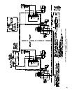
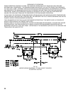
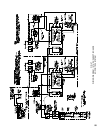
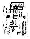
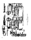
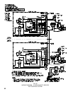
8. EECONTROLSYSTEM–5015Bthru5026B
The5015Bthru5026BboilersutilizetwoEEcontrol
systems that are interconnected electrically thru all
operating and safety controls. Should any of the
aforementioned controls break the power supply circuit,
both EE control systems would be de-energized. The
succeeding paragraphs describe the function and
operation of each EE Control System. Should a pilot
failure on one EE Control System occur, the other EE
Control System would not be affected. Thus main