


36
MS and nuts in the front holes and two #8 SMS in the
rear holes.
Connect the two wires from the Q179D pilot to the
RA890FProtectorelaySubbaseasfollows:
a.GroundWire(200ºC)tothe“G”terminal
b.Flamedetectorwire(Honeywell1298020)to“F”
terminal
c. ThermocoupleLeadtoL62Pilotstat.
Wire the pilotstat to the gas valve transformer and to the
V88AGasValvesusingthe105ºCwirefurnished,see
Fig.46or47.IfFootMountedtransformer,connectto
J-boxusingstraightconnector,BX,straightconnector
and ½” pipe coupling. Drill holes in Jacket and fasten
Transformer with SMS.
Run these wires to outside of jacket on underside of
manifold and secure in this position with Wire Ties
furnished to provide strain relief. Provide adequate
support and strain relief for wiring outside jacket.
4. COMPLETION OF WIRING – Connect power supply
fused disconnect switch, service switch, primary and
secondary side of gas valve transformer, primary side of
ignition transformer, and remaining controls – see Fig.
46–50forwiretypeandconnectionstobemade.All
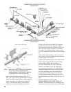
FIG. 33
INSTALLATION OF EO AND EE MOUNTING BRACKET AND CONTROLS
wiring must be adequately supported and strain relief
provided. All wiring including ground connections
must comply with the requirements of the authority
having jurisdiction and, in the absence of such, to the
National
ElectricalCode,ANSINFPANo.70-2005,
or the Canadian Electrical Code, C22.1, whichever is
applicable.
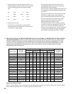
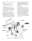
EE Control System
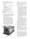
1. INSTALLATION OF “EE PANEL”, - Attach the EE
mounting bracket with Controls, see Fig. 33, to both
Upper and Lower Jacket End Panels. Two holes in
each Jacket Panel have been provided for this purpose.
Usetwo#10-32x½”MSandnutsinthefrontholes
and two #8 SMS in the rear holes. If Foot Mounted
Transformer,connecttoJ-boxusingstraightconnector,
BX, straight connector and ½” pipe nipple. Drill holes
in Jacket and fasten Transformer using SMS.
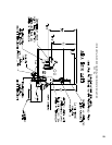
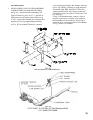
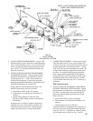
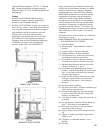
2. INSTALLATION OF PILOT PIPING – Install the
H91WA-4 pilot solenoid valve in the bottom center
knockoutoftheJ-boxusingconduitttingsfurnished,
see Fig. 34. Install RV-12LT regulator, (Packed in Gas
Train Carton) and 1/8” tee in the ¼” OD pilot tubing
as shown in Fig. 34.