


28
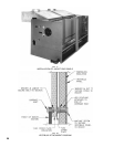
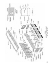
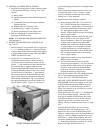
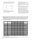
FIG. 25
STEAM TRIM AND CONTROLS
32. TIGHTEN ALL SHEET METAL SCREWS.
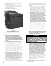
a. Install the following plates or labels which are found
in the Instruction Envelope. See Fig. 23 or 24 for
location.
(1) Rating Label
(2) Operating Instruction Plate (#8 SMS required to
fasten)
(3) Combustible Clearance Flooring & Adequate
Combustion Plate
(4) Minimum Service Clearance Label
(5) Burnham Logo – Apply to Top Panel
(6)BoilerVentilation/ForYourSafetyLabel
b. Proceed to Paragraph 33 (Steam Boilers) or
Paragraph 34 (Water Boilers).
NOTE: IF WATER BOILER, PROCEED DIRECTLY
TO Paragraph 34.
33. INSTALL STEAM TRIM AND CONTROLS, See
Fig. 7 and 25.
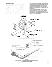
a. Pressure Gauge is to be installed with ½” nipple and
½”x¼”reducingcouplingin½”tappingprovided
in upper corner of End Section using wrench applied
to square shank on back of gauge. DO NOT APPLY
FORCE ON GAUGE CASE.
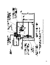
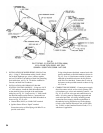
b.Install67BC-2LowWaterCut-Offor47-2
Combination Feeder and Low Water Cut-Off in
accordance with the Instructions packed with the
control.½”pipeextensionsareprovidedandmust
be installed in the ½” tappings adjacent to the
Pressure Gauge before the control can be mounted.
Unionsarefurnishedwiththe67BC-2LowWater
Cut-Off for ease of installation. 1” pipe tappings
have been provided in the End Sections for other
types of Low Water Cut-Offs and Low Water Cut-
Off & Feeder combinations. Fig. 25A illustrates
therequiredmountingelevationsforaM&M150
anda67MoatLWCO.Figure13Cillustratesa
typical steam piping arrangement for pumped return
systems.
c. Install Gauge Glass Fittings into ends of tees used
toconnectthe67BC-2or47-2Control.Ifother
control is furnished, install Gauge Glass Fitting
directlyinto½”pipeextensions.
d. Install Pressure Limit Controls as follows:
(1)Boilerequippedwith67BC-2LowWaterCut-
Off – Connect Pressure Limit furnished to ¼”
street ell and ¼” pigtail siphon. For installation
of second pressure limit (not furnished), bush
1½” pipe tapping in upper corner of End
Section. Connect Pressure Limit to this bushing
with ¼” pigtail siphon.
(2) Boiler equipped with Low Water Cut-Off other
than (1) above or with Low Water Cut-Off
Feeder Combination – Bush 1½” pipe tapping
in upper corner of End Section and connect
Pressure Limit furnished to this bushing with
¼” pigtail siphon. For installation of second
pressure limit bush any available tapping on
opposite end section that is above normal water
line. Connect Pressure Limit to this bushing
with ¼” pigtail siphon.
(3)Tightenlimitcontrolsbyusingwrenchonhex
ttingatbottomofcontrol.
(4)TheL404Pressuretrolmustbeaccurately
leveled for proper operation. It is level when the
leveling indicator hangs freely with its pointer
directlyovertheindexmarkinsidetheback
of the case. Level the controller by carefully
bending the steam trap (siphon loop).
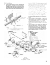
e.InstallPressureSafetyValvewithttingsfurnished,
into 1½” pipe tapping in upper corner of End
Section, see Fig. 12. DO NOT INSTALL A
SHUTOFF VALVE BETWEEN SAFETY VALVE
AND BOILER. If this boiler tapping is to be used
as Surface Blowoff, replace ell with tee and plug
open end of tee or valve off opening. Pressure
Safety Valve must be in leg of tee and in a vertical
position with handle up.
f.InstallBoilerDrainValveand3”x¾”Bushinginto
one of the two return tappings. The drain valve
may also be installed in return piping, but it must
be installed in the leg of a tee so that it is directly
opposite and as close as possible to the return
tapping. The leg of the tee must be at least 1½” pipe
size.
A Bottom Blowoff using a valve must also be
connectedtooneofthereturntappings.The¾”
Drain Valve may be used for Bottom Blowoff for
5009Borsmallerboilers,sinceanyBottomBlowoff
pipingorvalvesfor5009Borsmallerboilersmust
beatleast¾”.BottomBlowoffpipingandvalves
forBoilers5010Bthrough5021Bmustbeatleast
1”.BottomBlowoffpipingandvalvesfor5022B
Boilers and larger must be at least 1¼”.