


73
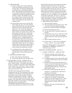
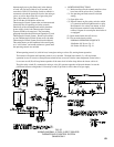
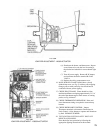
FIG. 58A
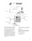
LOW FIRE ADJUSTMENT - V4062 ACTUATOR
(6)Shutdowntheburner,andthenrestart.Repeat
severaltimestobesurethelowresettingis
that desired and suitable for correct burner light
off.
(7)
Turn off power supply. Remove R-W jumper,
and reconnect the lead to terminal R on the
V9055A.
(8) Replace the wiring compartment cover.
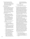
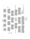
FIG. 58B
LOW FIRE ADJUSTMENT - V9055A ACTUATOR
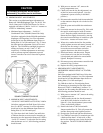
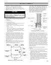
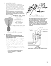
16.MAINBURNERFLAMESshouldhaveaclearly
denedinnercone,seeFig.63withnoyellowtipping.
Orange-yellow streak caused by dust should not be
confused with true yellow tipping.
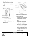
17. CHECK PILOT FLAME. Flame should be a blue
mediumhardameenvelopingapproximately3/8”of
theendofthethermocouple,amesensor,orsensing
probe,seeFig.64thru67.
18. CHECK THERMOSTAT OPERATION. Raise and
lower thermostat setting as required to start and stop
burners.
19. CHECK HIGH LIMIT CONTROL. Jumper
Thermostat terminals or thermostat Connections in
Limit Control. Allow burners to operate until shutdown
by limit. REMOVE JUMPER.
20. TESTIGNITIONSYSTEMSAFETYSHUT-OFF
DEVICE AS FOLLOWS:
Place the boiler into operation by following the
appropriate lighting instructions in this manual.