


40
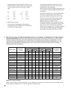
“THERMOCOUPLE CONTROL SYSTEM”
CANADA ONLY
FIG. 38
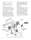
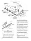
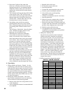
PILOT PIPING
THERMOCOUPLE CONTROL SYSTEM
CANADA ONLY
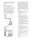
FIG. 39
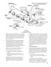
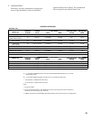
NOTE - TWO PILOT SAFETY SWITCHES REQUIRED
ON 15 SECT. AND LARGER BOILERS.
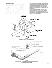
INSTALLATION OF PILOT SAFETY SWITCH
THERMOCOUPLE CONTROL SYSTEM
safetyswitchonbracketusingtwo#10-32x½”
MS. “IN” on pilot safety switch should be pointed
in the direction of the Gas Train to which the pilot
safety switch is to be connected, see Figure 39.
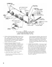
Using ¼” OD aluminum tubing, connect the pilot
shutoff valve installed in the manual shutoff valve
in the gas train, to the inlet of the RV-12LT regulator
(packed in Gas Train Carton). Regulator should be
above Gas Train and near front of boiler, see Figure 38.
Install 3/8” tee into outlet of regulator (USA boilers)
and, using ¼” OD aluminum tubing, connect outlet of
tee to “IN” connection on pilot safety switch, see Figure
38.
Using ¼” OD aluminum tubing, connect the outlet of
the
pilotsafetyswitchtothetubingorttingconnected
to the pilot burner, see Figure 38.
ConnectQ309thermocoupletopilotsafetyswitch.
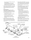
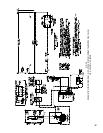
Connect power supply fused disconnect switch,
service switch, primary and secondary of
Gas Valve Transformer, gas valves, and other
controls
-seeFigure55or56forwiringtype
and connections to be made. All wiring must be
adequately supported and strain relief provided.
All wiring including ground connections must
comply with the requirements of the authority
having jurisdiction and, in the absence of such to
the
NationalElectricalCode,ANSINFPANo.70-
2005.
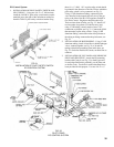
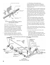
2. INSTALLATION OF GAS VALVE
TRANSFORMER AND COMPLETION OF
WIRING - Attach the bracket for mounting of the
junction
boxtothelowerfrontcorneroftheJacket