


12
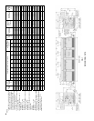
FIG. 8
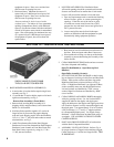
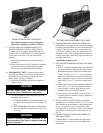
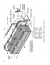
INSTALLATION OF BUILT-IN HEATER
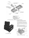
FIG. 9
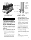
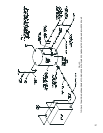
TESTING BOILER ASSEMBLY FOR LEAKS
Open Tankless Heater Carton(s) If Supplied.
Open Heater
Opening Cover Plate Carton(s).
9.
INSTALL BUILT-IN WATER HEATER(S) OR
HEATER OPENING COVER PLATE(S), See Fig.
8. Heater may be installed in either End Section or,
in some cases, in both End Sections. Heater Opening
Cover Plates are used to cover any unused heater
openings.
a.
Place rubber gasket against surface of plate and
align holes.
b. Place washer on each of 3/8” Cap Screws furnished
and insert cap screws through plate and gasket.
Start
allscrewsintapsbeforenaltightening.
10. HYDROSTATIC TEST - After the boiler sections
have been assembled, it is essential that the boiler be
hydrostatically
testedbeforethecanopy,uecover
plates, jacket, or piping is installed.
a.Plugallboilertappingsandllboilercompletely
with cold water.
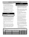
CAUTION
b. All completed boilers must satisfactorily pass the
prescribed hydrostatic test.
(1) STEAM BOILERS:
The assembled boiler must
be subjected to a hydrostatic test of 45 psig to 55
psig.
(2) HOT WATER BOILERS: The assembled boiler
must be subjected to a hydrostatic test of 75 psig
to 85 psig.
WARNING
11. EXAMINE BOILER CAREFULLY, INSIDE AND
OUTSIDE, to insure against leaks from cocked nipples
or through concealed breakage caused in shipping and
handling. This precaution is for your protection and
will simplify handling of necessary replacements and
adjustment claims. After making certain that there are
no leaks, drain boiler and remove plugs for boiler trim
and other connections.
Open Boiler Sealing Carton.
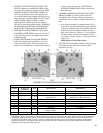
12
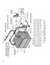
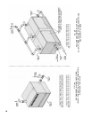
SEAL BETWEEN BOILER SECTIONS AND BASE,
seeFig.10.
a.Push¾”braidedceramicbreRope(furnished)into
gap between bottom of End Section and Low Base
End Panel until rope touches Front and Rear Base
Frames.Placethe1-1/2”x2”x5/8”steelspacers
between low base panel and section and in front of
rope – align holes. Secure section to low base end
panelwith3/8”-16x2”CapScrews,washersand
nuts.
b. Secure opposite end section to high base end panel
with3/8”-16x2”CapScrews,washersandnuts.
c. Apply Furnace Cement to gaps between section
assembly and base to make gas tight seal.
d. Check all joints between Boiler sections and use
remaining Furnace Cement or Sealer Compound to
make joints gas tight.
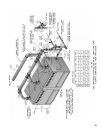
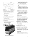
13. INSTALL FLUE COVER PLATES over cleanout
openings on Front and Rear of Boiler. Use ¼” Carriage
Boltsinstalledattopandbottomofueopeningsand
securewithwasherandjamnuttoprovideaxed
stud.Installuecoverplatesoverstudswithinsulation
against Boiler and secure with washers and nuts, see
Fig. 11.
14. CONNECT SUPPLY AND RETURN PIPING TO
HEATING SYSTEM.
CLEARANCES – Steam and Hot water pipes shall
have clearances of at least ½” from all combustible
construction.