


72
CAUTION
15. MINIMUM INPUT ADJUSTMENTS
This section covers Minimum Input Adjustments on
Honeywell V8944B Diaphragm Type “Lo-Hi-Lo” Gas
V
alves,HoneywellV5055BFluidPowerGasValves
equippedwitheitheraV4062A“Lo-Hi-Lo”Actuatoror
aV9055A“Modulating”Actuator.
a. Minimum Input Adjustments – “Lo-Hi-Lo”
Combination Valve, V8944B (Natural Gas Only)
On boilers equipped with the V8944B combination
diaphragm valve/regulator, Low Fire Adjustment
should not be less than Minimum Input shown on
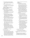
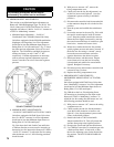
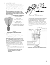
Rating Plate (1/3 of full rated input). Fig. 57 shows
the outlet pressure adjustment screws for low and
high
re.TheV8944Blowandhighrepressure
settingsarefactorysetat0.8”and3.5”W.C.
respectively. If further adjustments are necessary,
remove pressure regulator adjustment caps and
insert a screwdriver to raise or lower the regulator
pressure.
c. MINIMUM INPUT ADJUSTMENTS –
MOTORIZED “MODULATING” ACTUATOR,
V9055A
On boilers equipped with Fluid Power Valves that
have “Modulating” Actuators, Low Fire Adjustment
should not be less than Minimum Input shown on
Rating Plate (1/3 of full rated input).
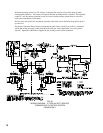
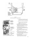
Fig. 58B shows the Low Fire Adjusting Screw
forincreasingordecreasinglowreinputonthe
HoneywellV9055A“Modulating”Actuator.To
adjustthelowresettingaftertheburnersare“on”,
the following procedure should be used.
(1) With power to actuator “off”, remove the wiring
compartment cover.
(2)Checktomakesurethelowreadjustmentis
set at MAX (full clockwise) to insure a safe
light-off.(Lowreadjustmentispresetatthe
factory in the MAX position.)
(3)RemovetheleadtoV9055AterminalR.
Jumper terminal R to W. This will prevent the
actuatorfromgoingtothehighreposition.
(4) Energize the system and light the main burner.
(5) Use a Phillips screwdriver, or standard type with
abladenomorethan3/16inchwide,toturn
thelowreadjustingscrewforthedesiredlow
reposition.DONOTPUSHINWARDON
SCREW.
FIG. 57
V8944B COMBINATION VALVE
(1)
With power to actuator “off”, remove the
wiring compartment cover.
(2)
Checktobesurethelowreadjustmentisset
atMAXtoinsureasafelight-off.(Lowre
adjustment is preset at factory in the MAX
position.)
(3) Disconnect the controller lead from terminal #4
ontheactuatortokeepthevalveinthelowre
position.
(4) Start the system and establish the main burner
ame.
(5) Loosen the setscrew in the cam (Fig. 58A) with
the special wrench taped to inside of actuator
cover. Keep the wrench seated in the setscrew.
Rotate the cam slightly downward (by moving
the wrench toward the base of actuator) to open
bleed valve. Actuator will start to close.
(6)Whenvalvereachesdesiredlowreposition,
quickly tighten setscrew and remove wrench. If
thedesirelowresettingis“missed”,merely
loosen the setscrew and rotate cam in the
opposite direction to the desired set point.
(7) Shut down burner, and then restart. Repeat
severaltimestobesurethelowresetting
is that desired and suitable for correct burner
lightoff. Readjust if necessary.
(8) Disconnect power and reconnect controller lead
removed in step (3) above.
(9) Replace the wiring compartment cover.
b. MINIMUM INPUT ADJUSTMENTS –
“LO-HI-LO”MOTORIZEDACTUATOR,V4062A
On boilers equipped with Fluid Power Valves that
have “Lo-Hi-Lo” Actuator, Low Fire Adjustment
should not be less than Minimum Input shown on
Rating Plate (1/3 of full rated input).
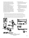
Fig. 58A shows the Limit Switch Cam and Scales
to indicate direction to rotate cam for increasing or
decreasinglowreinputontheHoneywellV4062A
“Lo-Hi-Lo”Actuator.Toadjustthelowresetting
after the burners are “on”, the following procedure
should be used.