


65
(2) PILOT FAILURE
(a) Flame rod supervision of the Q179D pilots
occurs only during the activating cycle (call
for heat) since it is during this period that the
operatingcontrolisenergizingtheRA890F
relays. If pilot failure occurs during this period
on one of the Q179D pilots the main gas valves
controlledbythatparticularRA890Fwillclose
within0.8second.TheRA890Fwilllock
out of safety within 15 seconds and the “Pilot
Flame Failure Lamp” will be activated. The
burnerscontrolledbytheotherRA890Fwill
continue to burn.
(b) If pilot failure occurs on one of the Q179D
pilots during the “off” cycle of the operating
control,theRA890Frelaywillnotbepowered,
therefore,thereisnoelectronicamerod
supervision. This is due to the utilization of a
thermocoupleineachQ179Dmodiedpilot
which controls its own pilot safety switch. This
thermocouplewillcoolin45to90seconds
de-energizing the pilot safety switch which
interrupts the circuit between the terminal #5
andthegasvalves.Inadditiontheowof
gastothepilotisshutoffand100%shutoff
is achieved. If the operating control calls for
heatduringthisperiod,theRA890Frelaywill
immediatelysensetheabsenceofpilotame
and the relay will lock out on safety within 15
seconds and the “Pilot Failure Alarm Light”
will be activated as described in (a) above.
(c) Assuming the pilot on the opposite side is
burning, the gas valves on that side will open
andmainamewillbeignitedonthatside
only.
d. SHUTDOWN INSTRUCTIONS
(1) Turn off all switches on both panels.
(2) Close manual shut-off valves and pilot valves.
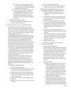
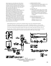
11. EEPCONTROLSYSTEM–5006Bthru5014B
The EEP Control System functionally is the same as
theEEControlSystem.TheRA890FProtectorelay,
however, is installed in a prewired control cabinet along
with a terminal strip, “main power” switch, “main gas
valves” switch, “main power” lamp, “main gas valves”
lamp, and “pilot failure” lamp.
TheEEPControlSystemutilizesanRA890F
ProtectorelayandaQ179CRecticationPilot,which
inadditiontoapilotburnerandrectifyingamerod
amedetectortoprovepilot,includesanignition
electrode for spark ignition of the pilot. A Webster
612-6A7Transformersuppliesthehighvoltagespark
potential.Oncepilotameisproven,ignitionstopsbut
pilotamecontinuesaslongasthereisa“callforheat”
(intermittent electrically ignited pilot).
TheRA890FProtectorelayPrimaryControlisanon-
programming amplifying relay which when used with
the Q179C Pilot provides solid state electronic Flame
Safeguard Protection that will not allow the main
gas valves to open on “call for heat” or that will shut
down main burners and turn off “main gas valves”
lampwithin0.8secondifpilotameisnot“proved”.
Protectorelay will lockout on safety shutdown within
15secondsifthereisapilotamefailureonstartor,if
duringthe“run”cycle,pilotameisnotre-established.
“Pilot failure alarm lamp” will come on. Since #3
terminal in the Protectorelay is de-energized at end of
safety switch timing, a solenoid valve in the pilot line
willcloseandthus100%shut-offisachieved.
a. OPERATING INSTRUCTIONS
(1) Turn off all panel switches.
(2) Turn off manual main and pilot gas valve. Wait
atleastve(5)minutesbeforeproceeding.
(3) Push safety switch reset button on this panel.
(4) Turn on manual pilot gas valve.
(5) Set operating control to desired temperature or
pressure.
(6)TurnonMain Power Switch. Main Power Light
will light. If all safety control and operating
control switches are closed, electronic pilot will
light.
(7) Turn on manual main gas valve(s).
(8) Turn on Main Gas Valve Switch to light main
burners. Main Gas Valve Lamp will light.
Proceed To Paragraph 15- Minimum Input
Adjustments (for diaphragm “Lo-Hi-Lo” or
motorized type gas valves).
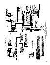
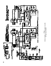
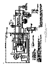
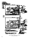
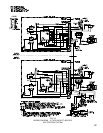
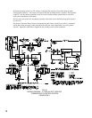
SEQUENCE OF OPERATION EEP – See Fig. 53
b.NORMALOPERATION–5006Bthru5014B
(1) When the operating control calls for heat,
terminals#6ofPanelandRA890FRelayare
energized.
(2)AcomponentcheckcircuitintheRA890FRelay
is activated which checks the electronic network
in the relay.
(3) Terminals #3 and #4 of the panel and relay are
energized. Terminal #3 opens pilot line solenoid
valve supplying gas to pilot. Terminal #4
energizes ignition transformer creating electric
spark ignition at pilot.
(4) Flame rod circuit between Q179C pilot and
terminal“F”onRA890Fprovespresenceof
pilotameelectronically.
(5) Terminal #4 to ignition transformer is de-
energizedafterameisprovenatQ179C.
(6)Terminal#5onRA890Fisenergizedand
supplies power to the main gas valves. “Main
Gas Valve” panel lamp will light providing
“Main Gas Valve” switch is “ON” (circuit
closed).
(7) Main gas valves open and main burners are
lighted by pilot.