


11
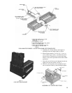
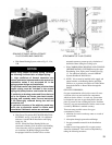
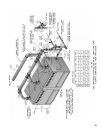
e. DRAW UP CENTER SECTION SLOWLY AND
EVENLY, tightening each DRAW-UP ROD a little
at a time so that sections are equally spaced. KEEP
NIPPLES ALIGNED WITH NIPPLE PORTS. If
necessary, tap Nipples lightly with a blunt tool or
rod to keep Nipples from cocking while Sections are
being drawn up. DO NOT DRAW UP SECTION(S)
WHEN NIPPLES ARE COCKED. Continue
tightening Draw-Up Rods equally until Sections
meet iron-to-iron on the ground surface. BUMPING
OUTER EDGES OF SECTION WITH WOODEN
BLOCK WILL EASE DRAW-UP OPERATION.
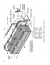
f. KEEP DRAW-UP ROD THREADS, NUTS AND
WASHERS LUBRICATED with grease or heavy oil
to prevent damage to rods and threads and to make
assembling easier.
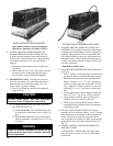
g. USING A PINCH BAR, insert WOOD WEDGES
under last Center Section assembled so as to raise
itjustaboveBoilerBase.Thiswillkeepthenext
section to be assembled above the base, thus making
it easier to join and draw-up. MOVE WOOD
WEDGES FORWARD EACH time a Section has
been drawn up.
7. ASSEMBLE REMAINING END SECTION WITH
DRAW-UP RODS in a manner similar to that for
assembling Center Sections. Remove wedges from
under Boiler. Be sure Boiler is aligned and seated on
Base.
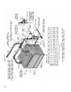
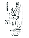
a. After section assembly is completed install 5/8” tie
rods from tie rod bundle through the upper lug holes
in the front of Boiler and Lower lug holes in the rear
ofBoilersectionsandtightenuntiltheyarenger
tightonly,toallowforexpansion.Thisisnecessary
in order to allow clearance for installation of Flue
coverplates.Finally,remove¾”draw-uprodsfrom
nipple ports.
Open Steam or Water Trim Carton
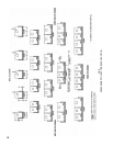
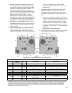
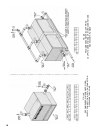
8. USE THE PLUGS IN THIS CARTON to plug tappings
inEndSectionsthatwillnotbeutilizedonnal
installation, see Fig. 7.
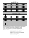
FIG. 7
PURPOSE OF TAPPINGS AND THEIR LOCATIONS
PURPOSE OF TAPPINGS
1
Location
Tapping Per
End Section
Size Steam Boilers Water Boilers
A 1 3” Supply Supply
B 1 3” Return Return
C
2
1 1-1/2”
Pressure Operating Control
(Bushed to 1/4”)
Temperature Operating Control (less heater)
Bushed to 3/4”; Plug (with heater)
D 1 1/2” Pressure Gauge Theraltimeter
E 2 1/2” Water Gauge, LWCO & Pressure Limit Plug
F 1 3/8” Try-Cock (Special Order) ----
G
3
1 ---- Cover Plate Cover Plate or Tankless Heater
H 1 1” See Note 4 See Note 4
J 1 1-1/2”
Indirect Water Heater
Supply or Return
----
K 1 3/4” Indirect Water Heater Limit ----
1
Tappings on both end sections are identical - Recommend trim be installed in left end section or on same end as gas train.
2
This tapping is used for safety valve and surface blowoff (steam boilers) and safety relief valve (water boilers) on end not equipped with trim.
3
Temperature operating control location on tankless heater equipped boilers. Also alternate operating control location, tapped cover plate.
4
If using a oat type LWCO, feeder or pump controller on a steam boiler that does not use quick connect hook up ttings, install between
tappings H and return B. Use opposite return B for system return connection. Water boilers using a probe LWCO must mount probe in
supply pipe above boiler without any stop valves.