


59
burners on the unaffected side would ignite on a “call
for heat” and would continue to operate until the
operating control was satised.
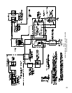
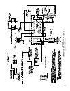
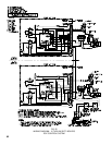
The EE Control System utilizes and RA890F
Protectorelay and a Q179C Rectication Pilot, which
in addition to a pilot burner and rectifying ame rod
ame detector to prove pilot, includes an ignition
electrode for spark ignition of the pilot. A Webster
612-6A7 Transformer supplies the high voltage spark
potential. Once pilot ame is proven, ignition stops but
pilot ame continues as long as there is a “call for heat”
(intermittent electrically ignited pilot).
The RA890F Protectorelay Primary Control is a
non-programming amplifying relay which when used
with the Q179C Pilot provides solid state electronic
Flame Safeguard Protection that will not allow the
main gas valves to open on “call for heat” or that will
shut down main burners within 0.8 second if pilot
ame is not “proved”. Protectorelay will lock out on
safety shutdown within 15 seconds if there is a pilot
ame failure on start or, if during the “run” cycle, pilot
ame is not re-established. Since #3 terminal in the
Protectorelay is de-energized at end of safety switch
timing, a solenoid valve in the pilot line will close and
thus 100% shut-off is achieved.
a. OPERATING INSTRUCTIONS
(1) Make sure all Manual Main Shut-off Valves and
all Pilot Valves have been off for at least ve
minutes.
(2)
Set Operating and Limit Controls to desired
settings.
(3) Turn all Manual Main Shut-off Valves and Pilot
Valves to Open Position.
(4) Turn on Main Electric Switch and Service
Switch. Pilots will automatically light main
burners.
Proceed to Paragraph 15- Minimum Input
Adjustments (for diaphragm “Lo-Hi-Lo” or
motorized type gas valves)
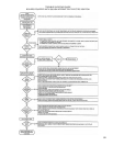
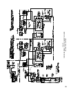
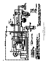
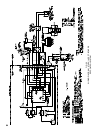
SEQUENCE OF OPERATION EE – See Fig. 50
a. NORMAL OPERATION – 5015B thru 5026B
1. When the operating control calls for heat,
terminal #6 of each RA890F Protectorelay is
energized.
2. A component check circuit in each RA890F
Protectorelay is activated which checks the
electronic network of the relay.
3. Terminals #3 and #4 of each RA890F relay are
energized. Terminal #3 opens the pilot line
solenoid valve supplying gas to the Q179C
pilot. Terminal #4 energizes ignition transformer
creating electric spark ignition at the Q179C
pilot.
4. Flame rod circuit between each Q179C pilot and
terminal “F” on its respective RA890F proves
presence of ame electronically at its Q179C
pilot.
5.
Terminal #4 of each RA890F and the ignition
transformer connected to it is de-energized.
6. Terminal #5 on each RA890F is energized
supplying power to its respective main gas
valves.
7. Main gas valves open and main burners are
ignited by the pilot ames.
8. When the operating control is satised, terminals
6 and all other terminals on both RA890F relays
are de-energized. The main gas valves and pilot
valve for each gas train are closed and main
burners and pilot burner ames are extinguished.
b. SAFETY SHUTDOWN
1. SAFETY SWITCH CIRCUIT
If limit control, low water cut-off or any
other electrical safety switch opens, power
to terminal 6 and all other terminals on both
RA890 Relays is interrupted de-energizing the
main gas valves and pilot valves and the main
gas burners and pilot burners are immediately
extinguished. Normal operation can be resumed
when the cause of the safety switch malfunction
is corrected. Make sure all manual resets are
activated where applicable.
2. PILOT FAILURE
(a) Pilot failure can occur during the start and
operating cycle of the boiler. Any pilot
failure on either of the Q179C Electronic
Pilots, after ignition of pilot ame will close
the pilot valve and the main gas valves
controlled by that particular RA890F relay
in 0.8 second. The burners controlled by the
other RA890F will continue to burn.
(b) For 15 seconds after failure of a Q179C
pilot, the relay through terminals #3 and #4
will attempt to re-establish pilot ame. If no
pilot ame can be sensed by the ame rod
circuit in 15 seconds, terminals #3 and #4
are de-energized, and the relay will lock out
on safety.
(c) Pilot failure is caused by the following:
(1) Complete loss of gas supply.
(2) Poor ignition spark caused by low
voltage, poor ground connection, faulty
wiring, and possibly a defective ignition
transformer.
(3) Low gas pressure will prevent ame rod
circuit from sensing pilot ame properly.
(4) Unusually strong secondary air drafts
can blow the pilot ame away from the
ame rod momentarily causing nuisance
shutdown.
(5) A pilot line solenoid valve will not open
because of faulty wiring, low voltage, or
possibly the valve is defective.