


39
made. All wiring must be adequately supported and
strain relief provided.
All wiring including ground connections must
comply with the requirements of the authority
having jurisdiction and, in the absence of such to the
NationalElectricalCode,ANSINFPANo.70-2005.
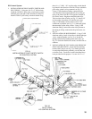
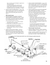
4. INSTALLATION OF BLEED PIPING – Using ¼” OD
aluminum tubing, install a bleed line on both diaphragm
valves,connecttogether,seeFig.25or26,andrun
tubing to bleed line protruding from inside base, see
Fig.36.
EEP Control System
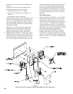
1. INSTALLATION OF “EEP PANEL” IGNITION
TRANSFORMER AND WIRING OF PILOT – Mount
the Electronic Control Panel and Ignition Transformer
on a wall adjacent to the Gas Train. Connect the three
wires from the Q179C pilot as follows:
a.GroundWire(200ºC)to#12terminalofterminal
strip in Electronic Control Panel.
b.Flamedetectorwire(Honeywell1298020)to#11
terminal strip in Electronic Control Panel.
c.IgnitionCable(Honeywell1061012)tothe
secondary (high voltage) terminal of the Ignition
Transformer.
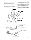
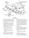
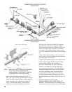
2. INSTALLATION OF PILOT PIPING – Install the
H91WA-4pilot solenoid valve in the bottom center
knockoutoftheJ-boxusingconduitttingsfurnished,
see Fig. 34. Install RV-12LT regulator, (Packed in Gas
Train Carton) and 1/8” tee in the ¼” OD pilot tubing as
shown in Fig. 37.
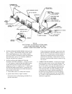
3. INSTALLATION OF BLEED PIPING – Using ¼” OD
aluminum tubing, install a bleed line on both diaphragm
valves,connecttogether,seeFig.25or26,and,onUSA
boilers, run tubing to bleed line protruding from inside
base, see Fig. 37. On boilers installed in Canada, run
bleed line to outdoors.
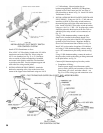
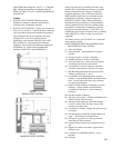
4. INSTALLATION OF GAS VALVE TRANSFORMER
AND COMPLETION OF WIRING – Attach the
bracketformountingofthejunctionboxtothelower
front corner of the Jacket Upper End Panel using
two#10-32x½”MSandnuts.Mountjunctionbox
tobracketusing#8SMS,seeFig.25or26.Install
Transformeronjunctionbox.
a. Completion of Wiring -
Connect power supply fused disconnect switch
service switch, primary and secondary of Gas Valve
Transformer, gas valves, and other controls – see
Fig. 53 or 54 for wiring type and connections to be
made. All wiring must be adequately supported and
strain relief provided.
All wiring including ground connections must
comply with the requirements of the authority
having jurisdiction and, in the absence of such to the
NationalElectricalCode,ANSINFPANo.70-2005.
Thermocouple Control System
1. INSTALLATION OF PILOT SAFETY SWITCH
ANDPILOTPIPING-Usingtwo#10-32x2”MS
andnuts,installtheL62GB-3Cpilotsafetyswitch
bracket on the manifold just to the right of the
mainburnerwithpilot.InstallL62GB-3Cpilot
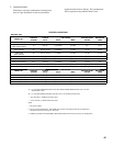
NOTE: PILOT PIPING DUPLICATED ON 15 SECTION AND LARGER BOILERS.
FIG. 37
PILOT PIPING
EEP CONTROL SYSTEM