225
Introduction to the Quaternary Pump
Setting the 8-bit Configuration Switch
Switches 1 in down and 2 in up position define that the RS-232C parameters
will be changed. Once the change has been completed, the instrument must
be powered up again in order to store the values in the non-volatile memory.
Use the following tables for selecting the setting which you want to use for
RS-232C communication. The number 0 means that the switch is down and 1
means that the switch is up.
One start bit and one stop bit are always used (not selectable).
Per default, the module will turn into 19200 baud, 8 data bit with no parity.
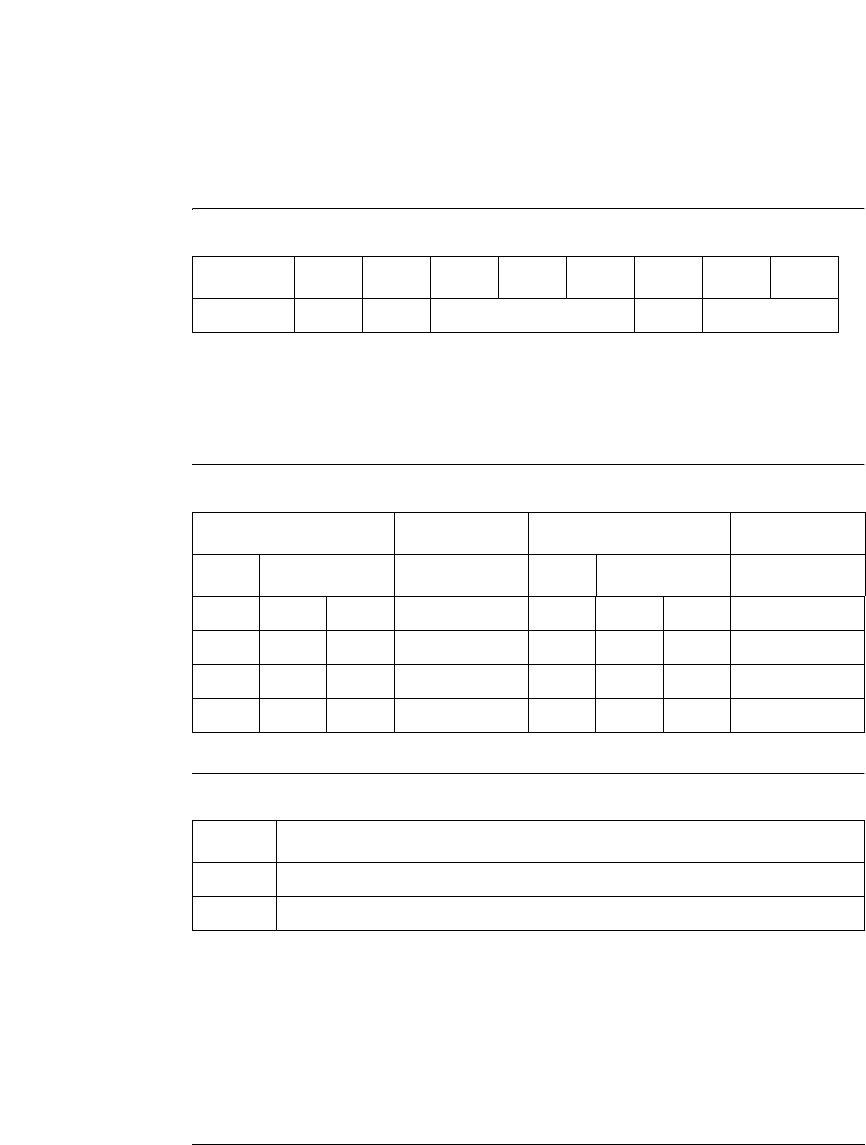
Table 37 Communication Settings for RS-232C Communication
Mode Select12345678
RS-232 0 1 Baudrate Data Bits Parity
Table 38 Baudrate Settings
Switches Baud Rate Switches Baud Rate
345 345
0 0 0 9600 (default) 1 0 0 9600
0 0 1 1200 1 0 1 14400
0 1 0 2400 1 1 0 19200
0 1 1 4800 1 1 1 38400
Table 39 Data Bit Settings
Switch 6 Data Word Size
0 7 Bit Communication
1 8 Bit Communication


