


RTAC-SVX01F-EN 89
Operating Principles
some fans are shut off to maintain the pressure differential. Fan staging depends on
the chiller load, evaporator pressure, condenser effectiveness, ambient temperature,
and numbers and sizes of fans installed on the circuit.
The algorithm pre-starts fans (based on ambient and water temperatures) when a
circuit starts the compressor. (For rare conditions such as during some pull-downs, a
steady fan state would either violate the 60 psid (4.2 bar) setpoint or cause a high
pressure cut-out; in those conditions a fan will cycle on and off.)
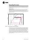
For up to two minutes after chiller start-up, the setpoint is 35 psi (2.45 bar) difference,
and then before the controls adjust gradually over half a minute up to 60 psi (4.2 bar).
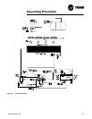
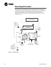
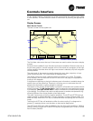
Expansion Valve
Pressure drop occurs in an electronic expansion valve. The unit controller (CH530)
uses the valve to regulate the flow through the liquid line to match the flow produced
by the compressor. The valve has a variable orifice that is modulated by a stepper
motor.
High pressure, subcooled liquid refrigerant enters the expansion valve from the liquid
line. As refrigerant passes through the valve the pressure is dropped substantially,
which results in vaporization of some of the refrigerant. The heat of vaporization is
supplied by the two phase mixture resulting in low temperature low pressure
refrigerant which is supplied to the evaporator (state 4) to provide cooling.
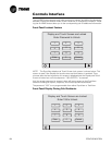
Evaporator
The evaporator is composed of a liquid-vapor distributor and falling film evaporator.
A liquid-vapor refrigerant mixture enters the distributor (state 4). The mixture is
distributed over the length of the evaporator tubes (state 4b). Liquid is evenly
distributed over the length of the evaporator tubes by the two-phase distribution
system. A portion of the liquid boils as it falls by gravity from tube to tube, wetting all
the tubes of the evaporator. To ensure that the tubes at the bottom of the evaporator
do not experience “dry out,” a liquid pool is maintained in the bottom few inches of
the bundle. Tubes located in the bottom of the evaporator will evaporate the liquid
refrigerant by boiling (pool boiling).
Heat is transferred from the water or glycol inside the tubes to the liquid refrigerant
as the film of refrigerant evaporates on the surface of the tube. Thin film heat transfer
requires a smaller temperature difference for a given amount of heat transfer than
nucleate boiling, which is the heat transfer process used in flooded evaporators.
Hence, efficiency is enhanced by the use of falling film evaporation. Additionally, the
evaporator requires less refrigerant than a comparable flooded evaporator and the
evaporator boils the entire refrigerant supply at constant pressure. Refrigerant vapor
exits the evaporator through the suction line (state 1).
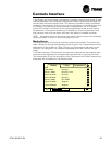
Oil System
Screw compressors require large quantities of oil for lubricating and sealing the rotors
and lubricating the bearings. This oil is mixed with refrigerant at the discharge of the
compressor. To enhance the performance of the heat exchanger surfaces an oil
separation system is placed into the discharge line. The oil separator is located
between the compressor and the condenser. It separates oil using highly efficient
centrifugal force. Approximately 99.5% of the oil is removed from the refrigerant in
the separator.
Oil that is removed from the refrigerant falls by gravity into the oil sump. This oil is
directed back to the compressor through the oil lines. Internal to the compressor is a
high efficiency filter to clean the oil before it is delivered to the rotors and bearings.
Once oil is injected into the compressor rotors it mixes with the refrigerant again and
is delivered back to the discharge line.