


86 RTAC-SVX01F-EN
Operating Principles
This section contains an overview of the operation and maintenance of RTAC units
equipped with CH530 control systems. It describes the overall operating principles of
the RTAC design.
Refrigeration Cycle
The refrigeration cycle of the RTAC chiller is similar to that of the RTAA air cooled
water chiller. The exception is that the evaporating and condensing temperatures have
been increased to allow for optimization of the chiller and reduced foot print. The
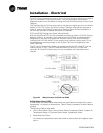
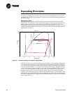
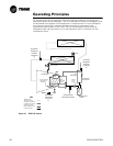
refrigeration cycle is represented in the pressure enthalpy diagram in
Figure 33. Key
state points are indicated on the figure. The cycle for the full load ARI design point is
represented in the plot.
Figure 33 Pressure Enthalpy (P-h) diagram of RTAC chiller
0 20 40 60 80 100 120 140
P (psia)
137 F
126 F
106 F
39 F
R134a
30
50
100
200
500
600
h (btu/lb)
1
1b
2
2b
3
3b
4
4b
(58 C)
(52 C)
(41 C)
(4 C)
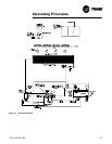
The RTAC chiller uses a shell and tube evaporator design with refrigerant evaporating
on the shell side and water flowing inside tubes having enhanced surfaces (states 4
to 1). The suction lines and bolt pads are designed to minimize pressure drop.(states
1 to 1b). The compressor is a twin-rotor helical rotary compressor designed similarly
to the compressors offered in other Trane Screw Compressor Based Chillers (states
1b to 2). The discharge lines include a highly efficient oil separation system that
virtually removes all oil from the refrigerant stream going to the heat exchangers
(states 2 to 2b). De-superheating, condensing and sub-cooling is accomplished in a fin
and tube air cooled heat exchanger where refrigerant is condensed in the tube (states
2b to 3b). Refrigerant flow through the system is balanced by an electronic expansion
valve (states 3b to 4).