


78 RTAC-SVX01F-EN
Installation - Electrical
NOTE: Exceptions are listed below.
When going from Stop to Auto, the EWP relay is energized immediately. If evaporator
water flow is not established in 4 minutes and 15 sec., the CH530 de-energizes the
EWP relay and generates a non-latching diagnostic. If flow returns (e.g. someone else
is controlling the pump), the diagnostic is cleared, the EWP is re-energized, and
normal control resumed.
If evaporator water flow is lost once it had been established, the EWP relay remains
energized and a non-latching diagnostic is generated. If flow returns, the diagnostic is
cleared and the chiller returns to normal operation.
In general, when there is either a non-latching or latching diagnostic, the EWP relay is
turned off as though there was a zero time delay. Exceptions (see above table)
whereby the relay continues to be energized occur with:
A Low Chilled Water Temp. diagnostic (non-latching) (unless also accompanied by an
Evap Leaving Water Temperature Sensor Diagnostic)
or
A starter contactor interrupt failure diagnostic, in which a compressor continues to
draw current even after commanded to have shutdown
or
A Loss of Evaporator Water Flow diagnostic (non-latching) and the unit is in the AUTO
mode, after initially having proven evaporator water flow.
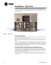
Alarm and Status Relay Outputs (Programmable Relays)
A programmable relay concept provides for enunciation of certain events or states of
the chiller, selected from a list of likely needs, while only using four physical output
relays, as shown in the field wiring diagram. The four relays are provided (generally
with a Quad Relay Output LLID) as part of the Alarm Relay Output Option. The relay’s
contacts are isolated Form C (SPDT), suitable for use with 120 VAC circuits drawing
up to 2.8 amps inductive, 7.2 amps resistive, or 1/3 HP and for 240 VAC circuits
drawing up to 0.5 amp resistive.
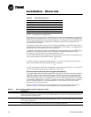
The list of events/states that can be assigned to the programmable relays can be
found in
Table 21. The relay will be energized when the event/state occurs.
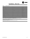
Table 20 Pump Relay Operation
Chiller Mode Relay Operation
Auto Instant close
Ice Building Instant close
Tracer Override Close
Stop TImed Open
Ice Complete Instant Open
Diagnostics Instant Open
Table 21 Alarm and Status Relay Output Configuration Table
Description
Alarm - Latching This output is true whenever there is any active diagnostic that requires a manual reset to clear, that
affects either the Chiller, the Circuit, or any of the Compressors on a circuit. This classification does not
include informational diagnostics.
Alarm - Auto Reset This output is true whenever there is any active diagnostic that could automatically clear, that affects
either the Chiller, the Circuit, or any of the Compressors on a circuit. This classification does not include
informational diagnostics.
Alarm This output is true whenever there is any diagnostic affecting any component, whether latching or auto-
matically clearing. This classification does not include informational diagnostics