


50 RTAC-SVX01F-EN
Installation - Mechanical
Remote Evaporator Option
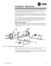
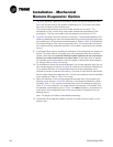
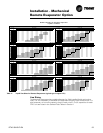
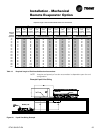
7. Figure 26, drawing 1 depicts an installation where the remote evaporator eleva-
tion is the same as that of the outdoor condensing unit. The suction and liquid
lines are horizontal or down flowing only.
The suction and liquid lines can be put under ground or in a trench. The
temperature of the suction lines must never exceed the temperature of the
compressor. The line can be below the compressors a maximum of 15 ft.
8. Figure 26, drawing 2 shows a variation to drawing 1. The remote evaporator and
outdoor condensing unit are at the same elevation but interconnecting piping may
be installed up to 15 feet above the base elevation. Refer to
Table 13 to determine
the required length of the suction accumulator line. A full size suction accumula-
tor is required at the evaporator and 50% of the value is required at the condens-
ing unit.
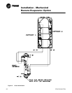
9. A refrigerant drain valve is installed at the bottom of the evaporator for freeze pro-
tection. This drain valve is a normally open, pilot operated valve which remains
closed unless there is a potential freezing situation detected via low evap temper
-
atures or low water temperatures or a power failure. If the drain valve is opened
the installed suction accumulator must be capable of holding the entire evapora
-
tor charge. Refer to Table 13 for sizing.
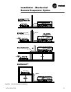
10. For installations where the remote evaporator is at a lower elevation than the out-
door condensing unit as shown in Figure 26, drawing 3, the elevation difference is
not to exceed 100 feet. An inverted liquid line trap at the condensing unit is
required to prevent unwanted free cooling. The apex of the liquid line trap should
be at a height above the condenser coils. A suction accumulator must be installed
at the evaporator. Refer to
Table 13 for sizing.
11. When the elevation of the remote evaporator exceeds that of the outdoor con-
densing unit as shown in Figure 26, drawing 4, the elevation difference is deter-
mined by Table 11. The suction accumulator line must be installed according to
Table 13. It is very important, for proper control and operation of the chiller, that
the elevation requirements given in Table 11 are not exceeded. It should also be
noted that in this configuration the suction accumulator is installed at the con-
densing section.
Note: The height is limited by the available subcooling.
12. Compressor & oil separator heaters must be on at least 24 hours prior to com-
pressor start.