


RTAC-SVX01F-EN 41
Installation - Mechanical
Debris, trash, supplies etc. should not be allowed to accumulate in the vicinity of the
unit. Supply air movement may draw debris into the condenser coil, blocking spaces
between coil fins and causing coil starvation. Special consideration should be given to
low ambient units. Condenser coils and fan discharge must be kept free of snow or
other obstructions to permit adequate airflow for satisfactory unit operation.
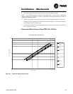
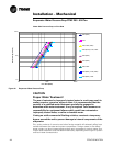
In situations where equipment must be installed with less clearance than recom-
mended, such as frequently occurs in retrofit and rooftop applications, restricted air-
flow is common. The Main Processor will direct the unit to make as much chilled
water as possible given the actual installed conditions. Consult your Trane sales engi
-
neer for more details.
NOTE: If the outdoor unit configuration requires a variance to the clearance dimen-
sions, contact your Trane Sales Office Representative. Also refer to Trane Engineering
Bulletins for application information on RTAC chillers.
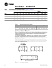
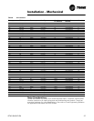
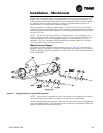
Unit Isolation and Leveling
For additional reduction of sound and vibration, install the optional neoprene isolators.
Construct an isolated concrete pad for the unit or provide concrete footings at the unit
mounting points. Mount the unit directly to the concrete pads or footings.
Level the unit using the base rail as a reference. The unit must be level within 1/4-in (6
mm) over the entire length and width. Use shims as necessary to level the unit.
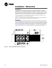
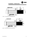
Neoprene Isolator Installation
1. Secure the isolators to the mounting surface using the mounting slots in the iso-
lator base plate. Do not fully tighten the isolator mounting bolts at this time.
2. Align the mounting holes in the base of the unit with the threaded positioning
pins on the top of the isolators.
3. Lower the unit onto the isolators and secure the isolator to the unit with a nut.
Maximum isolator deflection should be 1/4 inch (6 mm).
4. Level the unit carefully. Fully tighten the isolator mounting bolts.
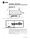
Drainage
Provide a large capacity drain for water vessel drain-down during shutdown or repair.
The evaporator is provided with a drain connection. All local and national codes apply.
The vent on the top of the evaporator waterbox is provided to prevent a vacuum by
allowing air into the evaporator for complete drainage.
Evaporator Water Piping
Thoroughly flush all water piping to the unit before making the final piping connec-
tions to the unit.
Evaporator Piping
Components and layout will vary slightly, depending on the location of connections
and the water source.
CAUTION
Evaporator Damage!
The chilled water connections to the evaporator are to be “victaulic”
type connections. Do not attempt to weld these connections, as the
heat generated from welding can cause microscopic and macroscopic
fractures on the cast iron waterboxes that can lead to premature failure
of the waterbox. To prevent damage to chilled water components, do
not allow evaporator pressure (maximum working pressure) to exceed
150 psig (10.5 bar).