


42 RTAC-SVX01F-EN
Installation - Mechanical
Provide shutoff valves in lines to the gauges to isolate them from the system when
they are not in use. Use rubber vibration eliminators to prevent vibration transmission
through the water lines. If desired, install thermometers in the lines to monitor enter
-
ing and leaving water temperatures. Install a balancing valve in the leaving water line
to control water flow balance. Install shutoff valves on both the entering and leaving
water lines so that the evaporator can be isolated for service.
CAUTION
Use Piping Strainers!
To prevent evaporator damage, pipe strainers must be installed in the
water supplies to protect components from water born debris. Trane is
not responsible for equipment-only-damage caused by water born
debris.
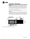
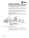
“Piping components” include all devices and controls used to provide proper water
system operation and unit operating safety. These components and their general loca
-
tions are given below.
Entering Chilled Water Piping
• Air vents (to bleed air from system).
• Water pressure gauges with shutoff valves.
• Vibration eliminators.
• Shutoff (isolation) valves. Thermometers (if desired).
• Clean-out tees.
• Pipe strainer.
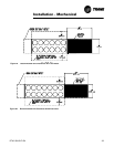
Leaving Chilled Water Piping
• Air vents (to bleed air from system).
• Water pressure gauges with shutoff valves. Vibration eliminators.
• Shutoff (isolation) valves.
• Thermometers.
• Clean-out tees.
• Balancing valve.
• Flow Switch
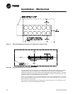
Evaporator Drain
A1/2 inch drain connection is located under the outlet end of the evaporator waterbox.
This may be connected to a suitable drain to permit evaporator drainage during unit
servicing. A shutoff valve must be installed on the drain line.
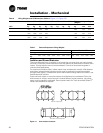
Evaporator Flow Switch
Specific connection and schematic wiring diagrams are shipped with the unit. Some
piping and control schemes, particularly those using a single water pump for both
chilled and hot water, must be analyzed to determine how and or if a flow sensing
device will provide desired operation.
Follow the manufacturer’s recommendations for selection and installation proce-
dures. General guidelines for flow switch installation are outlined below
1. Mount the switch upright, with a minimum of 5 pipe diameters of straight hori-
zontal run on each side. Do not install close to elbows, orifices or valves.
NOTE: The arrow on the switch must point in the direction of flow.