


RTAC-SVX01F-EN 81
Installation - Electrical
permit the ice building mode to be reentered until the unit has been switched out of
ice building mode (open 5K18 contacts) and then switched back into ice building
mode (close 5K18 contacts.)
In ice building, all limits (freeze avoidance, evaporator, condenser, current) will be
ignored. All safeties will be enforced.
If, while in ice building mode, the unit gets down to the freeze stat setting (water or
refrigerant), the unit will shut down on a manually resettable diagnostic, just as in
normal operation.
Connect leads from 5K18 to the proper terminals of 1U7. Refer to the field diagrams
which are shipped with the unit.
Silver or gold-plated contacts are recommended. These customer furnished contacts
must be compatible with 24 VDC, 12 mA resistive load.
External Chilled Water Setpoint (ECWS) Option
The CH530 provides inputs that accept either 4-20 mA or 2-10 VDC signals to set the
external chilled water setpoint (ECWS). This is not a reset function. The input defines
the set point. This input is primarily used with generic BAS (building automation
systems). The chilled water setpoint set via the DynaView or through digital
communication with Tracer (Comm3). The arbitration of the various chilled water
setpoint sources is described in the flow charts at the end of the section.
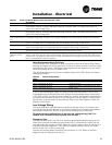
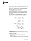
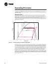
The chilled water setpoint may be changed from a remote location by sending either a
2-10 VDC or 4-20 mA signal to the 1U6, terminals 5 and 6 LLID. 2-10 VDC and 4-20
mA each correspond to a 10 to 65°F (-12 to 18°C) external chilled water setpoint.
The following equations apply:
If the ECWS input develops an open or short, the LLID will report either a very high or
very low value back to the main processor. This will generate an informational
diagnostic and the unit will default to using the Front Panel (DynaView) Chilled Water
Setpoint.
TechView Service Tool is used to set the input signal type from the factory default of
2-10 VDC to that of 4-20 mA. TechView is also used to install or remove the External
Chilled Water Setpoint option as well as a means to enable and disable ECWS.
External Current Limit Setpoint (ECLS) Option
Similar to the above, the CH530 also provides for an optional External Current Limit
Setpoint that will accept either a 2-10 VDC (default) or a 4-20 mA signal. The Current
Limit Setting can also be set via the DynaView or through digital communication with
Tracer (Comm 3). The arbitration of the various sources of current limit is described in
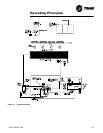
the flow charts at the end of this section. The External Current Limit Setpoint may be
changed from a remote location by hooking up the analog input signal to the 1 U6
LLID terminals 2 and 3. Refer to the following paragraph on Analog Input Signal
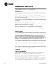
Wiring Details. The following equations apply for ECLS:
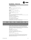
Voltage Signal Current Signal
As generated from external
source
VDC=0.1455*(ECWS)+0.5454 mA=0.2909(ECWS)+1.0909
As processed by CH530 ECWS=6.875*(VDC)-3.75 ECWS=3.4375(mA)-3.75
Voltage Signal Current Signal
As generated from external
source
VDC+0.133*(%)-6.0 mA=0.266*(%)-12.0
As processed by UCM %=7.5*(VDC)+45.0 %=3.75*(mA)+45.0