


88 RTAC-SVX01F-EN
Operating Principles
Refrigerant R134a
The RTAC chiller uses environmentally friendly R134a. Trane believes that responsible
refrigerant practices are important to the environment, our customers, and the air
conditioning industry. All technicians who handle refrigerants must be certified. The
Federal Clean Air Act (Section 608) sets forth the requirements for handling,
reclaiming, recovering and recycling of certain refrigerants and the equipment that is
used in these service procedures. In addition, some states or municipalities may have
additional requirements that must also be adhered to for responsible management of
refrigerants. Know the applicable laws and follow them.
R134a is a medium pressure refrigerant. It may not be used in any condition that
would cause the chiller to operate in a vacuum without a purge system. RTAC is not
equipped with a purge system. Therefore, the RTAC chiller may not be operated in a
condition that would result in a saturated condition in the chiller of –15°F (-26°C) or
lower.
R134a requires the use of specific POE oils as designated on the unit nameplate.
Important! The RTAC units must only operate with R-134a and Trane Oil 00048.
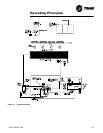
Compressor
The compressor is a semi-hermetic, direct-drive rotary type compressor. Each
compressor has only four moving parts: two rotors that provide compression and
male and female load-control valves. The male rotor is attached to the motor and the
female rotor is driven by the male rotor. The rotors and motor are supported by
bearings.
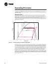
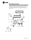
The helical rotary compressor is a positive displacement device. Refrigerant vapor
from the evaporator is drawn into the suction opening of the compressor (state 1b),
through a suction strainer screen across the motor (which provides motor cooling)
and into the intake of the compressor rotors. The gas is then compressed and
discharged through a check valve and into the discharge line (state 2).
There is no physical contact between the rotors and the compressor housing. The
rotors contact each other at the point where the driving action between the male and
female rotors occurs. Oil is injected into the rotors of the compressor, coating the
rotors and the compressor housing interior. Although this oil does provide rotor
lubrication, its primary purpose is to seal the clearance spaces between the rotors
and compressor housing. A positive seal between these internal parts enhances
compressor efficiency by limiting leakage between the high pressure and low
pressure cavities.
Capacity control is accomplished by means of a female step load-control valve and a
male control valve. The female step valve is the first stage of loading after the
compressor starts and the last stage of unloading before the compressor shuts
down. The male control valve is positioned by a piston cylinder along the length of the
male rotor. Compressor capacity is dictated by the position of the loading valve
relative to the rotors. When the valve slides toward the discharge end of the rotors
compressor capacity is reduced.
Condenser and Subcooler
The condenser and subcooler are similar to the condenser used in RTAA chillers. The
heat exchanger consists of 3/8” tubes that contain the refrigerant, large fins that are
in the air flow and fans that draw air through the fins. Heat is transferred from the
refrigerant through the tubes and fins to the air.
High pressure gas from the compressor enters the tubes of the condenser through a
distribution header (state 2b). As refrigerant flows through the tubes, the heat of
compression and cooling load are rejected to the air. In this process the refrigerant is
de-superheated, condensed (states 2b to 3) and finally subcooled (states 3 to 3b) to a
temperature slightly above the ambient air temperature. The subcooled liquid
refrigerant is collected in the leaving header where it is transferred to the liquid line
(state 3b).
A controls algorithm always runs as many fans as possible without reducing the
differential pressure (discharge minus suction) below the setpoint (60 psid or 4.2 bar).
If a warm enough ambient is sensed, all the fans will run. If the ambient is cooler,