


RTAC-SVX01F-EN 79
Installation - Electrical
Relay Assignments Using TechView
CH530 Service Tool (TechView) is used to install the Alarm and Status Relay Option
package and assign any of the above list of events or status to each of the four relays
provided with the option. The relays to be programmed are referred to by the relay’s
terminal numbers on the LLID board 1U12.
The default assignments for the four available relays of the RTAC Alarm and Status
Package Option are:
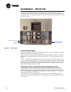
If any of the Alarm/Status relays are used, provide electrical power, 115 VAC with
fused-disconnect to the panel and wire through the appropriate relays (terminals on
1U12 (EUR=A4-5)). Provide wiring (switched hot, neutral, and ground connections) to
the remote annunciation devices. Do not use power from the chiller’s control panel
transformer to power these remote devices. Refer to the field diagrams which are
shipped with the unit.
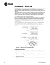
Low Voltage Wiring
The remote devices described below require low voltage wiring. All wiring to and
from these remote input devices to the Control Panel must be made with shielded,
twisted pair conductors. Be sure to ground the shielding only at the panel.
To prevent control malfunctions, do not run low voltage wiring (<30 V) in
conduit with conductors carrying more than 30 volts.
Emergency Stop
CH530 provides auxiliary control for a customer specified/installed latching trip out.
When this customer-furnished remote contact 5K14 is provided, the chiller will run
normally when the contact is closed. When the contact opens, the unit will trip on a
manually resettable diagnostic. This condition requires manual reset at the chiller
switch on the front of the control panel.
Connect low voltage leads to terminal strip locations on 1U4. Refer to the field
diagrams that are shipped with the unit.
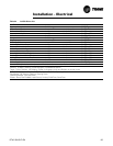
Alarm Ckt 1 This output is true whenever there is any diagnostic effecting Refrigerant Circuit 1, whether latching or
automatically clearing, including diagnostics affecting the entire chiller. This classification does not
include informational diagnostics.
Alarm Ckt 2 This output is true whenever there is any diagnostic affecting Refrigerant Circuit 2 whether latching or
automatically clearing, including diagnostics effecting the entire chiller. This classification does not
include informational diagnostics.
Chiller Limit Mode
(with a 20 minute fil-
ter)
This output is true whenever the chiller has been running in one of the Unloading types of limit modes
(Condenser, Evaporator, Current Limit or Phase Imbalance Limit) continuously for the last 20 minutes.
Circuit 1 Running This output is true whenever any compressors are running (or commanded to be running) on Refrigerant
Circuit 1, and false when no compressors are commanded to be running on that circuit.
Circuit 2 Running This output is true whenever any compressors are running (or commanded to be running) on Refrigerant
Circuit 2, and false when no compressors are commanded to be running on that circuit.
Chiller Running This output is true whenever any compressors are running (or commanded to be running) on the chiller
and false when no compressors are commanded to be running on the chiller.
Maximum Capacity
(software 18.0 or
later)
This output is true whenever the chiller has reached maximum capacity or had reached its maximum
capacity and since that time has not fallen below 70% average current relative to the rated ARI current
for the chiller. The output is false when the chiller falls below 70% average current and, since that time,
had not reestablished maximum capacity.
Table 21 Alarm and Status Relay Output Configuration Table
Description
Table 22 Default Assignments
Relay
Relay 1 Terminals J2 -12,11,10: Alarm
Relay 2 Terminals J2 - 9,8,7: Chiller Running
Relay 3 Terminals J2-6,5,4: Maximum Capacity (software 18.0 or later)
Relay 4 Terminals J2-3,2,1: Chiller Limit