


58 RTAC-SVX01F-EN
Installation - Mechanical
Remote Evaporator Option
Refrigerant Sensors
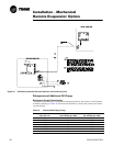
All necessary refrigerant devices, transducers and solenoids are factory installed and
wired to the evaporator terminal box.
Refrigerant Pressure Relief Valve Venting
ƽ WARNING
Hazardous Gases!
Consult local regulations for any special relief line requirements.
Refrigerant vented into a confined equipment room could displace
available oxygen to breathe, causing possible asphyxiation or other
serious health risks. Failure to follow these recommendations could
result in death or serious injury.
Vent pipe size must conform to the ANSI/ASHRAE Standard 15 for vent pipe sizing. All
federal, state, and local codes take precedence over any suggestions stated in this
manual.
All relief valve venting is the responsibility of the installing contractor.
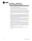
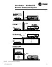
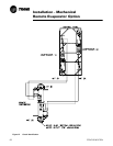
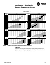
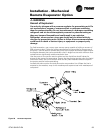
All RTAC remote evaporator units use evaporator pressure relief valves (Figure 29)
that must be vented to the outside of the building.
Relief valve connection sizes and locations are shown in the unit submittals. Refer to
local codes for relief valve vent line sizing information.
Caution
Equipment Damage!
Do not exceed vent piping code specifications. Failure to comply with
specifications may result in capacity reduction, unit damage and/or relief
valve damage.
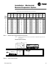
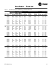
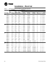
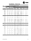
Relief valve discharge setpoints and capacities rates are given in Table 12. Once the
relief valve has opened, it will re-close when pressure is reduced to a safe level.
Once opened, relief valves may have a tendency to leak and must be replaced.
Pressure relief valve discharge capacities will vary with shell diameter and length and
also compressor displacement. Discharge venting capacity should be calculated as
required by ASHRAE Standard 15-94. Do not adjust relief valve setting in the field.
Valve Location Discharge
Setpoint
(psi)
Number of
Valves
Rated Capacity
per Relief Valve
(lba/min.)
Field Connection
Pipe Size (in NPT)
Factory
Shell Side
Connection (in)
Leak Test and Evacuation
After installation of the refrigerant piping, thoroughly test the system for leaks. Pres-
sure test the system at pressures required by local codes.
Table 15 Pressure Relief Valve Data
Evap 200 2 28.9 3/4 7/8 - 14