


RTAC-SVX01F-EN 75
Installation - Electrical
Installer-Supplied Components
Customer wiring interface connections are shown in the electrical schematics and
connection diagrams that are shipped with the unit. The installer must provide the
following components if not ordered with the unit:
• Power supply wiring (in conduit) for all field-wired connections.
• All control (interconnecting) wiring (in conduit) for field supplied devices.
• Fused-disconnect switches or circuit breakers.
• Power factor correction capacitors. (optional)
Power Supply Wiring
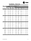
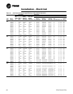
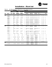
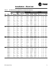
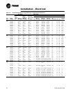
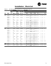
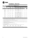
All power supply wiring must be sized and selected accordingly by the project
engineer in accordance with NEC Table 310-16.
ƽ WARNING
Hazardous Voltage w/Capacitors!
Disconnect all electric power, including remote disconnects before
servicing. Follow proper lockout/tagout procedures to ensure the power
cannot be inadvertently energized. For variable frequency drives or other
energy storing components provided by Trane or others, refer to the
appropriate manufacturer’s literature for allowable waiting periods for
discharge of capacitors. Verify with an appropriate voltmeter that all
capacitors have discharged. Failure to disconnect power and discharge
capacitors before servicing could result in death or serious injury.
Note: For additional information regarding the safe discharge of
capacitors, see PROD-SVB06A-EN or PROD-SVB06A-FR
All wiring must comply with local codes and the National Electrical Code. The
installing (or electrical) contractor must provide and install the system interconnecting
wiring, as well as the power supply wiring. It must be properly sized and equipped
with the appropriate fused disconnect switches.
The type and installation location(s) of the fused disconnects must comply with all
applicable codes.
CAUTION
Use Copper Conductors Only!
Unit terminals are not designed to accept other types of conductors.
Failure to use copper conductors may result in equipment damage.
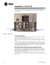
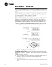
Cut holes into the sides of the control panel for the appropriately-sized power wiring
conduits. The wiring is passed through these conduits and connected to the terminal
blocks, optional unit-mounted disconnects, or HACR type breakers. Refer to
Figure
31.
To provide proper phasing of 3-phase input, make connections as shown in field
wiring diagrams and as stated on the WARNING label in the starter panel. For
additional information on proper phasing, refer to “Unit Voltage Phasing.” Proper
equipment ground must be provided to each ground connection in the panel (one for
each customer-supplied conductor per phase).