45
Module Current Consumption Section 2-6
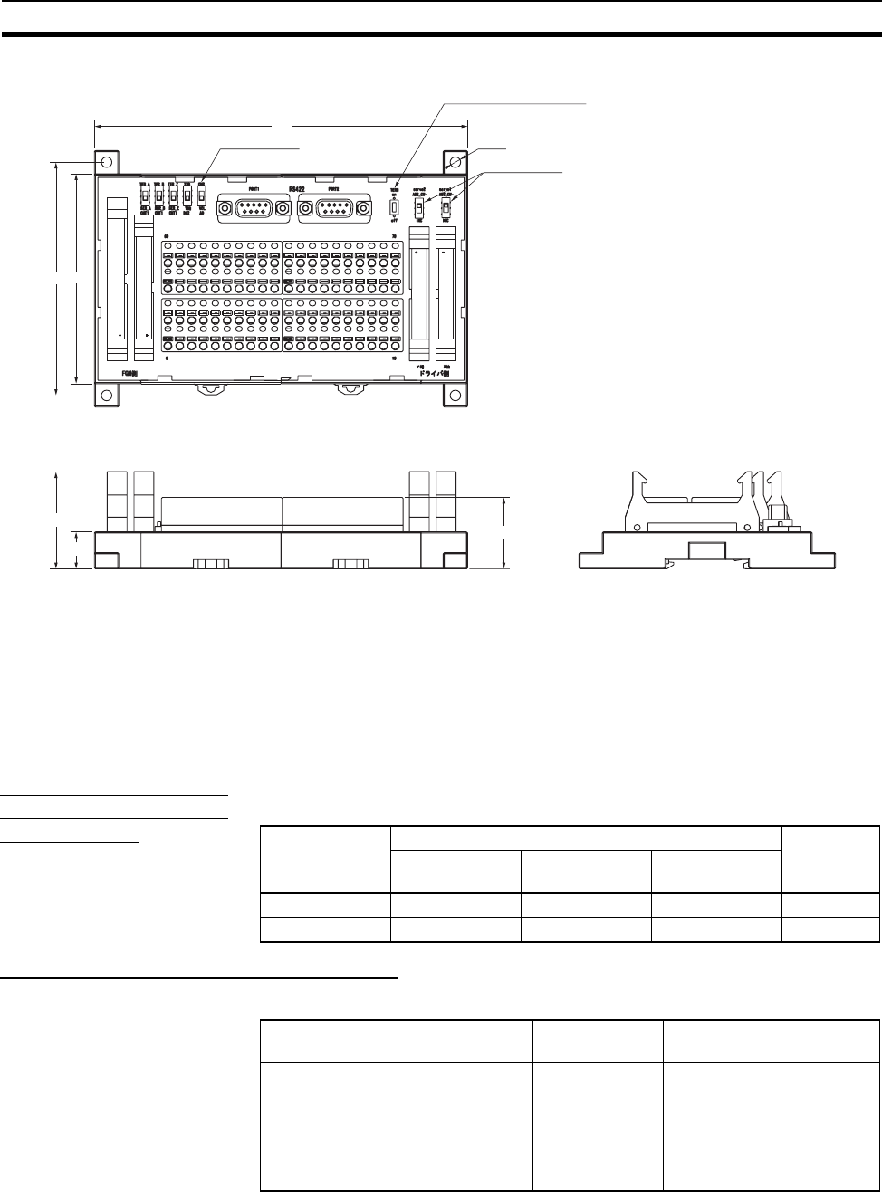
XW2B-80J7-1A Servo Relay Unit
2-6 Module Current Consumption
The amount of current/power that can be supplied to the Modules mounted in
the FQM1 is limited. Refer to the following tables when designing your system
so that the total current consumption of the mounted Modules does not
exceed the maximum current for each voltage system and the total power
consumption does not exceed the maximum for the Power Supply Unit.
Maximum Current and
Maximum Total Power
Consumption
The following table shows the maximum currents and power that can be sup-
plied by Power Supply Units to the Controller.
Current Consumption for Each Module
Current Consumption for 5-V System
Note The current consumption increases by 0.15 A/Module if NT-AL001 Link Adapt-
ers are used.
160
4.5 dia.
Phase B switches
Signal switches
Terminating resistance switch
100
90
41.7
15.9
30.7
Power Supply
Unit
Max. current consumption Max. total
power con-
sumption
5-V system
(internal logic)
24-V system
(analog)
24-V system
(service)
CJ1W-PA202 2.8 A 0.4 A None 14 W
CJ1W-PA205R 5.0 A 0.8 A None 25 W
Name Model 5-V system current
consumption (A)
Coordinator Module
Note The listed value includes the
current consumption for the
CX-Programmer.
FQM1-CM001 0.47 (See note.)
End Module FQM1-TER01 Included in Coordinator
Module current consumption


