288
Programming Appendix A
Computing the Cycle Time
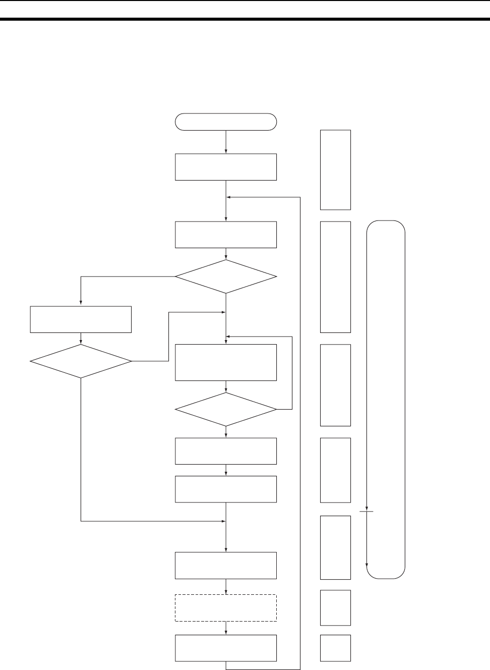
FQM1 Operation Flowchart
The Coordinator Module and Motion Control Modules process data in repeating cycles from the overseeing
processing up to peripheral servicing as shown in the following diagram.
NO
YES
Sets error flags
I/O refreshing
ERR indicator lit or
flashing?
Flashing (non-
fatal error)
Executes user pro-
gram (i.e., executes
cyclic task).
End of program?
Resets watchdog timer
and waits until the set
cycle time has elapsed
Calculates cycle time
Services Peripheral
Devices
Check OK?
Checks hardware and
user program memory
Checks Module
connection status.
Power ON
NO
YES
Overseeing processing Startup initialization
Cycle time
Program execution
Cycle time
calculation
Performs I/O refreshing
Periph-
eral
servic-
ing
Sync bus refreshing
Sync bus
refreshing
Lit (fatal error)


