295
Programming Appendix A
Calculation Example
Input ON delay: 0.03 ms
Overhead time: 0.193 ms
Instruction execution time: 0.001 ms
Output ON delay: 0.1 ms
Position of OUT: Beginning of program.
I/O Response Time for Pulse and Analog I/O
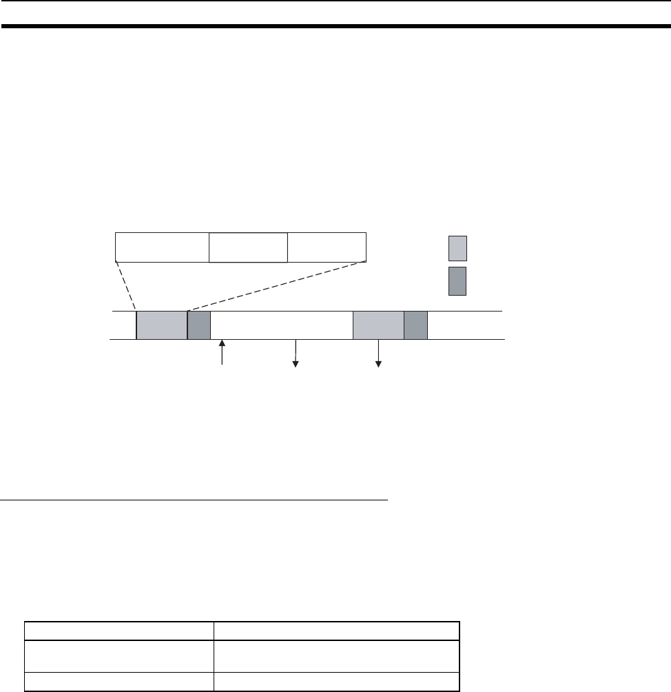
As shown in the following diagram, an MPU in the Motion Control Module directly controls pulse and analog I/O
processing with hardware. The cycle time for pulse and analog I/O is thus included in the cycle time of a Motion
Control Module. Hardware control means that the most recent data is handled for this I/O.
The pulse and analog input data read with the I/O refresh in one cycle will thus be used immediately and can
be output from the ladder program in the next cycle.
Interrupt Response Times
Motion Control Module Interrupt Response Times
Input Interrupt Tasks
The interrupt response time for an input interrupt task is the time required from when a built-in input on a
Motion Control Module turns ON (upward differentiation) or turns OFF (downward differentiation) until the input
interrupt task is actually executed. The interrupt response time for an input interrupt task would be the total of
the hardware and software response times given in the following table.
• Response Times for Built-in Inputs
Note (1) Input interrupt tasks can be executed during execution of the user program, I/O refresh, peripheral
servicing, or overseeing processes. (During user program execution, instruction execution is sus-
pended to execute the interrupt task.) The response time is not affected by the type of process being
executed when the input interrupt is generated. An input interrupt task, however, will not be executed
immediately if another interrupt task is already being executed. Execution of the next interrupt task
will wait until the current interrupt task has completed execution and then interrupt tasks will be ex-
ecuted in order of priority after the Software interrupt response time.
(2) For the FQM1-MMA21, interrupt processing is prohibited during analog I/O conversion. A minimum
of 72 to 130
µs will be required.
(3) If an interrupt occurs during an instruction that is processed using hardware, interrupt task execution
will be postponed until the instruction has finished execution. A minimum of 10
µs will be required.
The interrupt response time for an input interrupt task is shown below.
Input interrupt response time = Input ON delay + Software interrupt response time
Instruction execution
I/O refresh
Instruction execution
Overseeing Processing
Pulse inputs
read
Analog output
conversion
Analog input
conversion
Pulse/analog
input
Pulse/analog
output
Analog
output
Internal
processing
Item Description
Hardware response time Upward differentiation: 0.03 ms
Downward differentiation: 0.2 ms
Software response time 72 to 82 µs (See note 2.)


