


2. DESIGN
2
−
19
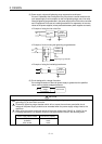
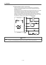
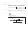
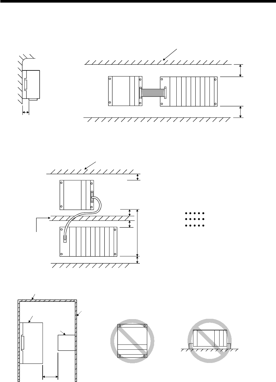
2.4.3 Installation
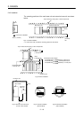
The mounting positions of the main base unit and extension base unit are shown
below.
Connector for SSCNET
40mm (1.57inch)
*1
Main base unit Extension base unit
30mm
(1.18inch)
min.
70mm
(2.76inch)
min.
Top of enclosure, wiring duct, or other components
Enclosure, etc.
Door
Contactor,
relay, etc.
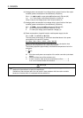
CPU module
100mm
(3.94 inch)
min.
Fig.2.1 Parallel Installation
*1: If a DIN rail is used, consider the mounting position of the DIN rail.
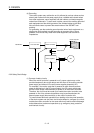
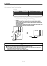
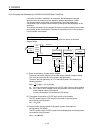
Duct height 50mm
(1.97inch) max.
30mm
(1.18inch) min.
70mm
(2.76inch) min.
30mm
(1.18
inch)
min.
*2
Top of enclosure,wiring duct, or other components
Extension base unit
Main base unit
70mm
(2.76inch) min.
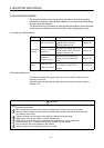
*2:Extension Cable Lengths
A1SC03B cable
A1SC12B cable
A1SC30B cable
280mm(11.02inch)max.
1100mm(43.3inch)max.
2900mm(114.17inch)max.
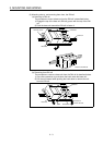
Fig.2.2 Series Installation
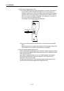
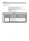
Fig.2.3 Clearance to Instruments
in Front of CPU module
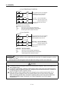
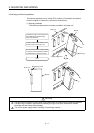
Fig.2.4 Vertical Installation
(
Not Permitted
)
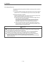
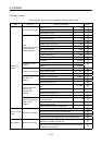
Fig.2.5 Horizontal Installation
(
Not Permitted
)