2. DESIGN
2
−
4
2.2 System Design
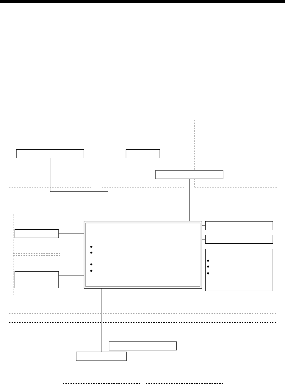
To exercise motion control and external I/O equipment control, the motion system
consists of the CPU module, main base unit and various modules such as the
power supply module, pulse generator/synchronous encoder modules and I/O
modules. Each module must be selected, set, and connected according to the
system specifications. Further, the motion system can connect to the graphic
operation system (GOT), exercise information control using a personal computer,
and connect to a control network which uses the MELSECNET so that the system
may be configured up to meet various applications.
Based on the following system configuration, this section explains the ways to
select the modules needed in designing the motion system and to set and connect
the modules, and the designing precautions.
MELSECNET system
Refer to Section
1.5.1(8).
OUT
Personal computer
Refer to Section 1.5.1(7).
Motion controller
SSCNET
MELSECNET(II)/10
Servo amplifier
Motor control
Refer to
Section 1.5.6(2).
MELSEC-A
I/O module
I/O control
SSCNET
Refer to Section 1.5.4(3).
Refer to Section 1.5.4(3).
Peripheral
device
Teaching
JOG operation
Teaching unit
Refer to Section 1.5.5(2).
Personal computer
Refer to Section
1.5.1(9).
SSCNET
Monitoring/OperationControl network Information control
RS422
(CPU front)
Stroke limit
Stop signal
Near-zero point DOG/Speed
-position changeover
command
Manual pulse generator
Synchronous encoder
Servo external signal
(Such as digital oscilloscope,
monitoring and recipe functions)
Independent motion system
I/O bus control
RS422 (CPU front)
Computer link
CPU module
Pulse generator/synchronous encoder interface
module (refer to Section 1.5.4(3))
Limit output module
Base, extension cable (refer to Section 1.5.3(3))
Program development


