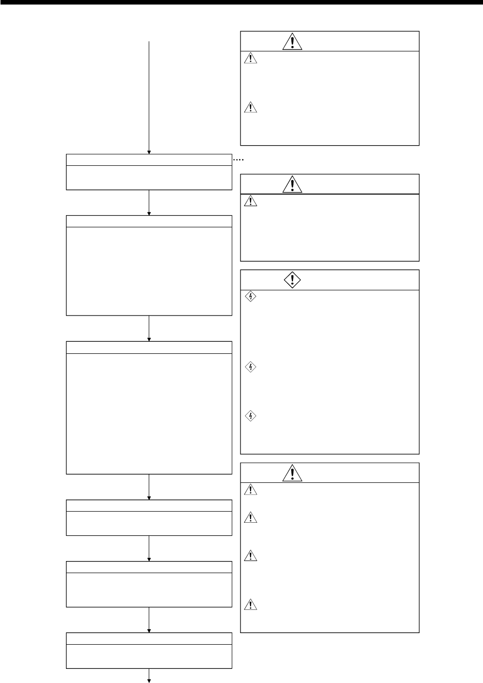
4. TRIAL RUN AND ADJUSTMENT
4
−
4
Install operating system
Install the positioning OS into the
CPU module from the peripheral device.
WARNING
Even if the power is tumed off, do not open
the front casing or terminal covers, except
to connect wiring or conduct scheduled
inspections. Charged components in the
controller or servo amplifier can cause
electric shocks.
See Section 4.3.
To avoid electric shocks, turn off the
power, wait at least ten minutes, then
check the voltage with a tester before
starting wiring or inspections.
Install controllers, servo amplifiers, and
servomotors before connecting wiring.
Otherwise, electric shocks or injury can
result.
CAUTION
Connect a leak breaker to the controller
and servo amplifier power supply.
Provide an extemal emergency stop circuit
to instantaneously stop operation and cut
off power.
Follow the conditions prescribed in this
manual and the product instrction manuals
when programming using the program
commands.
When programming, follow the conditions
prescribed in this manual regarding
devices which a fixed application.
CAUTION
Do not connect a phase-advancer
capacitor, surge absorber, or radio noise
filter (FR-BIF option) to the servo amplifier
output.
Ensure output teminals U, V, W, are
correctly connected. Abnomal servomotor
operation may result if the teminals are
incorrctly connected.
1)
CAUTION
Set parameter values to match the
controllers, servo amplifiers, servomotors,
and regenerative resistor models used.
Protective functions may not operate
correctly if the parameters are set
incorrectly.
[Install Mode]
Set positioning parameters
(1) Set the following positioning parameters
from the peripheral device:
(a) Fixed parameters
(b) Servo parameters
(c) Home position return data
(d) Limit switches
(e) Control data
Write motion programs
Create motion programs from the peripheral
device.
Create sequence programs
Create sequence programs from the
peripheral device to run the motion
programs.
(1) Check the wiring for the following
external inputs by monitoring at a
peripheral device or by using the LED
indicators.
(Input signals' PX0 to PXF)
(a) FLS (upper limit switch input)
(b) RLS (lower limit switch input)
(c) STOP (stop command)
(d) DOG/CHANCE (near-zero point dog,
speed/position switching commad)
Check external inputs to A172SENC
Write sequence programs
Write the created sequence programs to
CPU module with the peripheral device.
[Data Setting Mode]
[Monitor Mode]
[Programming Mode]
[Programming Mode]
[Sequence Mode]
2
)


