


1. SPECIFICATIONS OF MOTION SYSTEM COMPONENTS
1
−
40
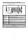
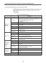
(3) Selection of A172SENC module and connection with external equipment
(a) Number of A172SENC modules
Determine the number of A172SENC modules according to the number of
control axes which use such external signals as upper and lower stroke limit and
near-zero point dog signals and the number of manual pulse
generators/synchronous encoders used.
You can use up to four modules for the A173UHCPU or only one module for the
A172SHCPUN or A171SHCPUN.
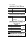
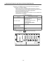
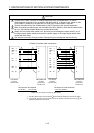
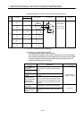
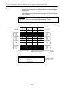
A172SENC Specifications
Signal/Connected External
Equipment
Usable Number per A172SENC
Upper stroke limit input
Lower stroke limit input
Stop signal input
Near-zero point dog/speed-position
change signal input
8 points
(for 8 axes)
Servo external signal
Tracking enable input: 1 point
Electromagnetic brake command
output: 1 point
Manual pulse
generator/incremental
synchronous encoder
(Voltage/differential output type)
1 unit
Serial absolute synchronous
encoder
1 unit
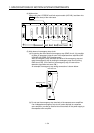
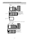
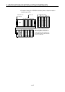
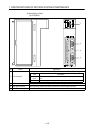
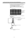
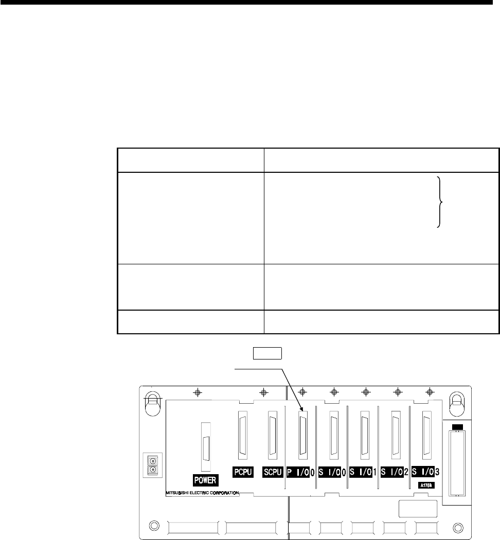
Load the A172SENC to P I/O (motion slot) of the main base.
OUT
Motion slot