


1. SPECIFICATIONS OF MOTION SYSTEM COMPONENTS
1
−
36
•
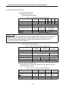
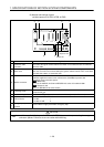
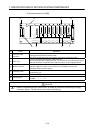
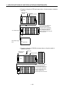
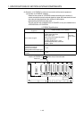
Example of using the A175B main base (when a 16-point module is loaded to
each slot)
Sequencer slot No.
CPU
Power supply
module
A168B extension base unit
Motion slot
0
00
0F
to
10
80
8F
to
8
90
9F
to
9
A0
AF
to
11
B0
BF
to
12
C0
CF
to
13
D0
DF
to
14
E0
EF
to
15
F0
FF
to
Main base unit
(A175B)
Vacant, 16 points 40 to 4F
Vacant, 16 points 50 to 5F
Vacant, 16 points 60 to 6F
Vacant, 16 points 70 to 7F
45
6
7
10
1F
to
20
2F
to
30
3F
to
123
Sequencer slot No.
1st extention stage
2
nd extention stage,
s
lot 0
(special unit)
GOT
100
11F
The I/O numbers indicated are
those set by automatic I/O
assignment. When empty slots
4 to 7 are set to 0 points (S0) in
the I/O assignment, the I/O
numbers of slot 8 of the extension
base are 40 to 4F.
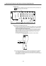
•
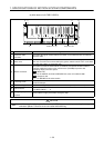
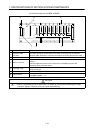
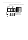
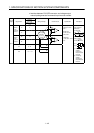
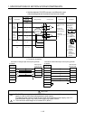
Example of using the A178B-S2 main base (when a 16-point module is
loaded to each slot)
Sequencer slot No.
CPU
Power supply
module
A1S68B extension base unit
Motion slot
0
00
0F
to
10
80
8F
to
8
90
9F
to
9
A0
AF
to
11
B0
BF
to
12
C0
CF
to
13
D0
DF
to
14
E0
EF
to
15
F0
FF
to
Main base unit
(A178B-S2)
Vacant, 16 points 40 to 4F
Vacant, 16 points 50 to 5F
Vacant, 16 points 60 to 6F
Vacant, 16 points 70 to 7F
4
5
6
7
10
1F
to
20
2F
to
30
3F
to
123
The I/O numbers indicated are
those set by automatic I/O
assignment. When empty slots
4 to 7 are set to 0 points (S0)
in the I/O assignment, the I/O
numbers of slot 8 of the
extension base are are 40 to 4F.