1. SPECIFICATIONS OF MOTION SYSTEM COMPONENTS
1
−
27
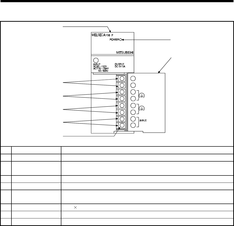
(b) A1S62PN power supply module names of parts
1)
3)
4)
5)
6)
7)
8)
N
100-240 VAC
(FG)
(LG)
2
DC24V 0.6A
24V
24G
2)
No. Name Application
1) POWER indicator Display indicator for 5 VDC power supply.
2)
24VDC, 24GDC
terminals
Supplies output modules which require 24 VDC internally (supplied through external
wiring).
3) FG terminal A grounding terminal connected with the shielding pattern on the printed circuit board.
4) LG terminal Ground for power supply filter, with 1/2 the electrical potential of the input voltage.
5)
Power supply input
terminals
Connect the 100 VAC or 200 VAC power supply to the power supply input terminals.
6) Terminal screws M 3.5 7
7) Terminal cover A cover to protect the terminal block.
8) Module fixing screws Screws to fix the module to the base unit.


