


2. DESIGN
2
−
8
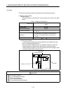
POINT
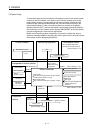
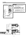
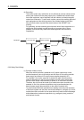
(1) *1 : 100 VAC power supply can also be used as
the power supply to the CPU module.
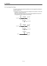
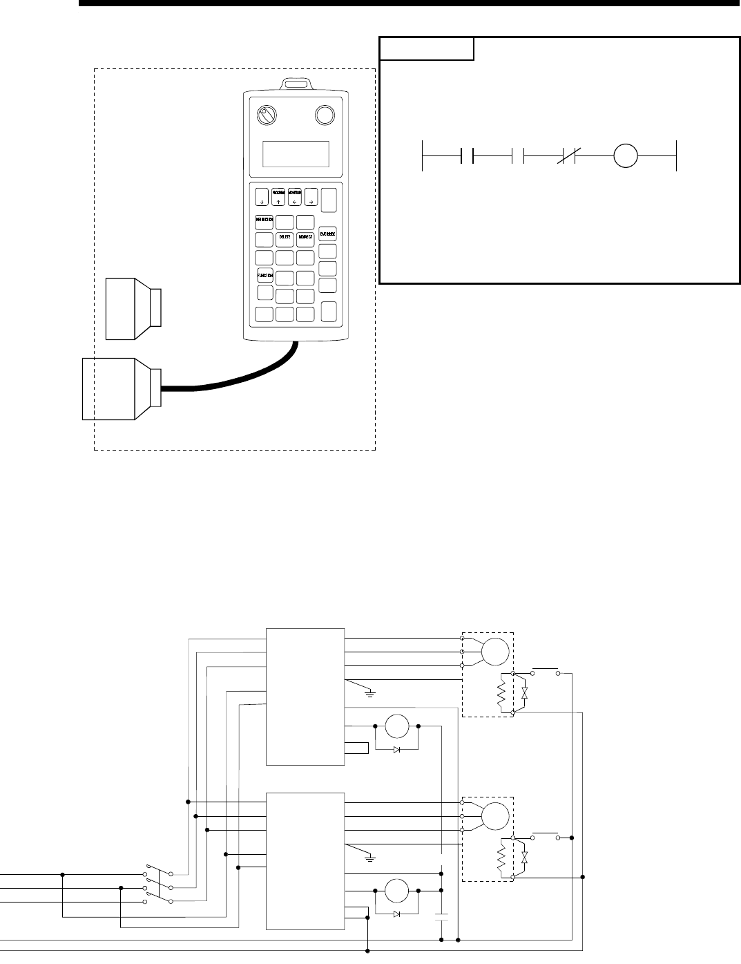
(2) *2 : Sequence program
M9036 M9074
Servo alarm/
Error detection
Ym
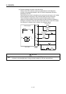
(3) *3 : It is also possible to use a full wave rectified
power supply as the power supply for the
electromagnetic brake.
(4) For details on connection of SSCNET cable and
termination resistors, refer to Section 1.5.6 (2).
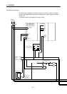
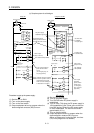
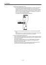
Outside of control board
A31SHORTCON
short-circuit
connector
(when A31TU-E is not
connected)
There is a deadman switch
on the rear side.
OR
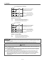
MITSUBISHI A31TU-E
InvalidValid
A31TU-E SV13 Ve
*Data *Monitor
*PROG *Test
Press the mode key.
Schematic
drawing of
front panel
Emergency Stop
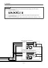
DATA TEST
STOP
STEP-
STEP+
RETURN
ERROR
RESET
GO
SHIFT
CAN
AXIS
NO.
JOG - JOG +
ITEM
#
8
CLEAR
SP
79
:
E
5
F
46
D
B
2
C
13
A
WRIT E
STORE
-
0.
MDI
MC
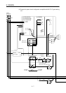
SM
U
V
W
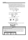
Ra12
Ra12
MR-J2S-B
/MR-J2-B
U
V
W
L1
L2
L3
L11
L21
COM
MER
EM1
SG
E
MC
Electro-
magnetic
brake
*3
Ground
Servo motor
Ra11
SM
U
V
W
Ra11
U
V
W
R
S
T
R1
S1
COM
MER
EM1
EM2
MR-H-BN
E
Servo motor
Electro-
magnetic
brake
*3