


4. TRIAL RUN AND ADJUSTMENT
4
−
5
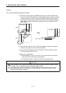
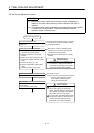
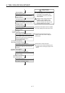
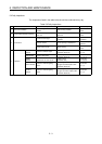
Write positioning data
Write the created sequence programs and
motion programs to CPU module with the
peripheral device.
CAUTION
If used in systems for which safety
standards apply (such as robot systems),
all controllers, servo amplifiers, and
servomotors must meet the prescribed
safety standads.
Configure safety circuits extemal to the
controller or servo amplifiers if their
abnomal operation could cause axis
motion in a direction other than the safe
operating direction for the system.
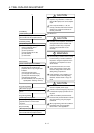
2)
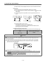
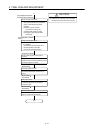
[Servo PC Mode]
Turn servo power on
Ensure emergency stop is ON, and turn on
power to servo amplifiers and servomotors.
Check Motor Rotation Directions
Check motor rotation directions are correct
for increased addresses and forward JOG
operation.
Check upper/lower stroke limits
Check that upper and lower stroke limits
operate correctly.
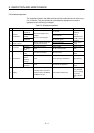
Reads and displays the servomotor and
servo amplifier model names from the servo
amplifier after they have been transferred to
the servo amplifier during initial
communications with it.
Servo Amplifier Communications Check
Check Motor Speeds
Check motor does not exceed rated speed
at maximum commanded speed.
3
)
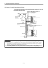
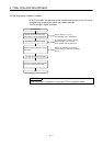
Check servo amplifiers
Check that mounted servo amplifiers
operate correctly.
Detected error description and servo amplifier
axis number displayed on initial check screen.
Compare the set servomotor and servo
amplifier model names with the displayed
model names.
Release brake on motor with brake.
If an error occurs, reset the emergency stop
in a status where an emergency stop can be
applied.
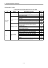
[Test Mode - Servo
Start-Up (Initial Check)]
[Test Mode - Servo
Start-Up (Model Name Check)]
[Test Mode - Servo Start-Up
(Motor Rotation Direction Check)]
[Test Mode - Servo Start-Up
(Upper/Lower Limit Switch Check)]
[Test Mode - Servo Start-Up
(Motor Speed Check)]