


1. SPECIFICATIONS OF MOTION SYSTEM COMPONENTS
1
−
50
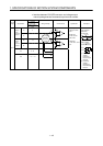
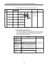
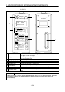
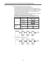
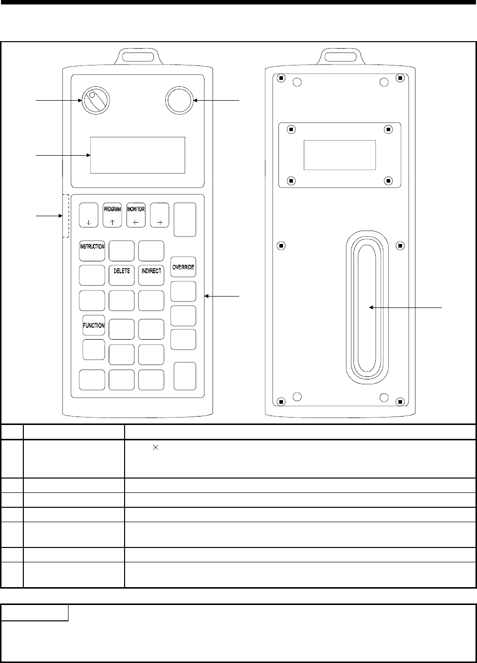
(b) A31TU-E
MITSUBISHI A31TU-E
1)
2)
4)
6)
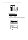
InvalidValid
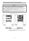
A31TU-E SV13 Ve
*Data *Monitor
*PROG *Test
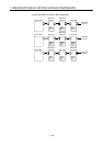
Press the mode key.
3)
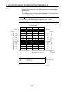
Schematic
drawing of
front panel
Emergency Stop
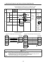
Schematic drawing
of rear panel
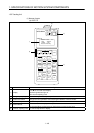
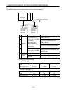
7)
DATA
TEST
STOP
STEP-
STEP+
RETURN
ERROR
RESET
GO
SHIFT
CAN
AXIS
NO.
JOG - JOG +
ITEM
#
8
CLEAR
SP
79
:
E
5
F
4
6
D
B
2
C
1
3
A
WRITE
STORE
-
0.
MDI
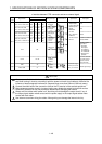
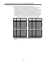
No. Name Application
1) Display
4-line
16-character LCD display
With back-lighted auto light off
With contrast adjusting knob
2) Emergency stop key Shuts off servo power to stop all operations.
3) Valid/Invalid switch Changes over the operations of the teaching box between valid and invalid.
4) Operation keys Operation key switches of the teaching box
5) Internal buzzer
Buzzer sounds when key input or any alarm occurs.
It is also possible to set the buzzer so that it does not sound for key input.
6) Contrast adjusting knob For contrast adjustment of display
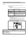
7) Deadman switch
Turns on the switch to enable servo operation: turns off the switch to shut off the servo
power.
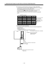
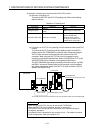
POINT
A dead-man switch is used for jogging operated from the teaching box. To operate the switch, press and
hold it down. Releasing the deadman switch turns off servo power, bringing the servo motor to an
immediate stop.