


1. SPECIFICATIONS OF MOTION SYSTEM COMPONENTS
1
−
37
•
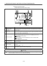
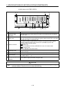
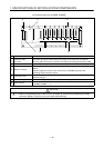
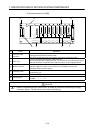
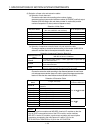
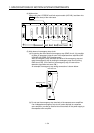
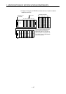
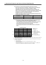
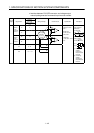
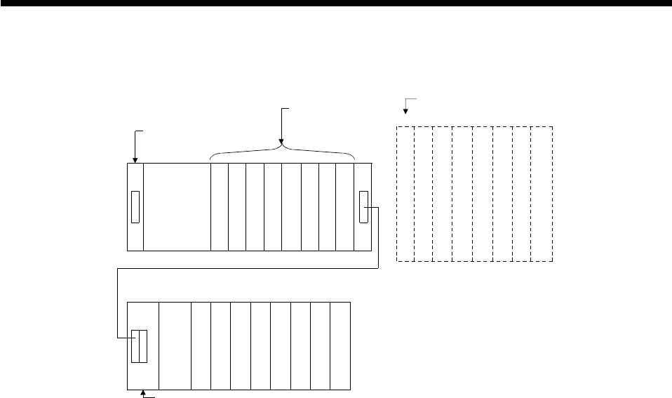
Example of using the A178B-S3 main base (when a 16-point module is
loaded to each slot)
CPU
Power supply
module
A1S68B extension base unit
Motion slot
10
80
8F
to
8
90
9F
to
9
A0
AF
to
11
B0
BF
to
12
C0
CF
to
13
D0
DF
to
14
E0
EF
to
15
F0
FF
to
Main base unit
(A178B-S3)
Vacant, 16 points 10 to 1F
Vacant, 16 points 20 to 2F
Vacant, 16 points 30 to 3F
Vacant, 16 points 40 to 4F
Vacant, 16 points 50 to 5F
Vacant, 16 points 60 to 6F
Vacant, 16 points 70 to 7F
1
234567
Vacant, 16 points 00 to 0F
0
Sequencer slot No.
The I/O numbers indicated are those
set by automatic I/O assignment.
When empty slots 0 to 7 are set to 0
points (S0) in the I/O assignment, the
I/O numbers of slot 8 of the extension
base are are 00 to 0F.